PG-FP5 APPENDIX D ELECTRICAL SPECIFICATIONS OF REMOTE INTERFACE
R20UT0008EJ0400 Rev. 4.00 Page 229 of 240
Jul 15, 2010
(2/2)
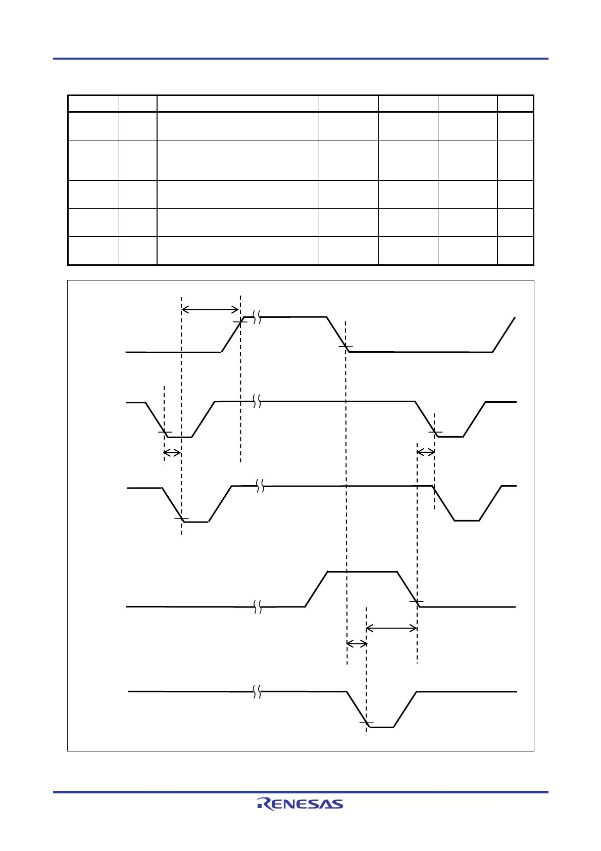
Pin name Symbol Parameter or Conditions MIN. TYP. MAX. Unit
tPBAIN
Time from the fall of the BANK signal until
the VRF or START signal can be input
1 ms
tPINBU
Time from the fall of the VRF, START or
ENTER signal until the rise of the BUSY
signal
100 ms
tPBUIN
Time from the fall of the BUSY signal until
the CLEAR signal can be input
5 ms
tPCLPE
Time from the fall of the CLEAR signal until
the fall of the PASS or ERROR signal
50 ms
tPPEBA
Time from the fall of the PASS or ERROR
signal until the BANK signal can be input
10 ms
BUS
t
PINBU
t
PBAIN
BANK0
BANK1
BANK2
t
PPEBA
ENTER
START
VRF
t
PBUIN
t
PCLPE
PASS
ERROR
CLEAR