2.11.16 Adjusting the leading edge registration in the ADF/SADF modes
Standard:
Between --3 and +5 mm (ADF mode)
Between --4 and +6 mm (SADF mode)
CAUTION
This procedure is required when the ADF
control board is replaced.
NOTE
Before following this procedure, adjust the leading
edge registrations in the platen (not ADF and
SADF) mode. (Refer to Adjusting the leading edge
registration of the Paper feed unit section.)
1. Set an original in the SADF set table and make a
copy.
2. Measure the difference in the leading edge
registration between the copy and original.
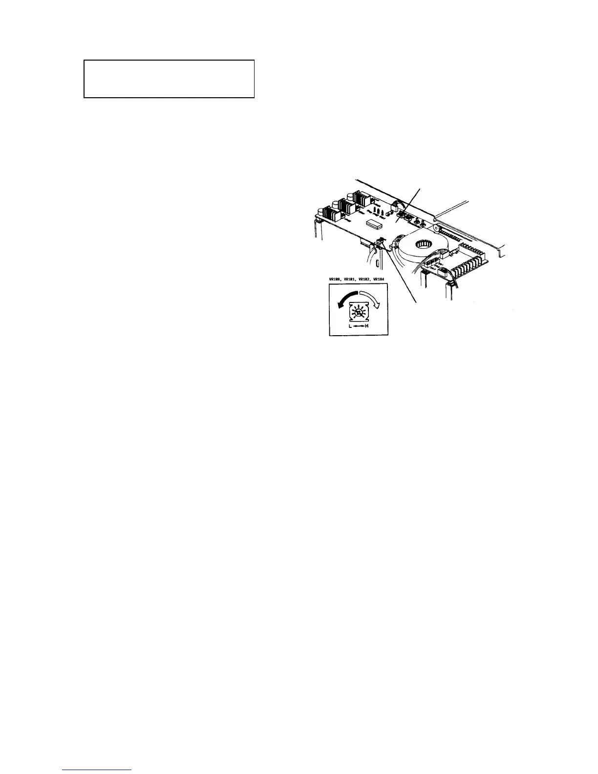
3. If the value is different from the standard, turn
VR104 on the ADF control board. Turn off the
main switch, and remove the ADF rear cover (7
plated screws) to access VR104.
NOTE
• Turn VR104 clockwise to move the leading
edge of the copy image backward.
• Turn VR104 counterclockwise to move the
leading edge of the copy image forward.
CAUTION
The ADF rear cover is made of metal. So, the
cover may touch electric elements on the
boards shorting them out when you remove the
cover. Be sure to turn off the main switch when
you remove the ADF rear cover.
4. Finally make more than 10 continuous copies to
check the variation. Be sure that all copies are
within the standard. If not, repeat the above step.
NOTE
• You do not need to check the leading edge
registration in the ADF mode if it is satisfied in
the SADF mode.
• In the ADF mode, originals are passed 7 mm
through the correct original stop position on the
exposure glass. Then, they return 12 mm to hit
their trailing edges against the original scale
and stop. When VR104 is turned, 7 mm
passed and 12 mm return, the amount in the
ADF mode also changes.
ADF control board
VR104