Item Description Setting Method
5-04 I/O test The following tests can be done.
(1) Output (operation) test for each
motor, solenoid, etc.
* Two or more items can be selected at
the same time for the test.
(2) Input test for each sensor.
* If a sensor or detection signal is
activated, the buzzer sounds.
(3) Combination of input and output tests
Press [5-04] of the system test menu.
⇓
Press one of the menu keys: [Motor]/[P.
Pack 1]/[P. Pack 2]/[Fan
Motor]/[Lamp/Sol.]/[Jam Sensor]/[Others].
⇓
Select output and input item(s) for each
page.
When you want to select other item(s),
move to another page by pressing the
menu key.
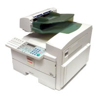
1. Motor
* Output test items
Main Main motor
OPC OPC motor
LCT Top LCT transport motor
Wire Wire cleaner motor (automatic stop after one cycle)
Dev. Development motor (after OPC is turned ON)
Toner Toner supply motor
Agitat. Agitator motor
CAUTION: To turn on the development motor, turn on the OPC motor first. This is to
prevent OPC damage.
* Input test items
Overload Main motor overload detection
Set OPC unit set detection
OPC Mark OPC sensor (home mark sensor only)
F Edge OPC sensor (front edge sensor only)
R Edge OPC sensor (rear edge sensor only)
Tracking Sector sensor
Overload Wire cleaner motor overload detection
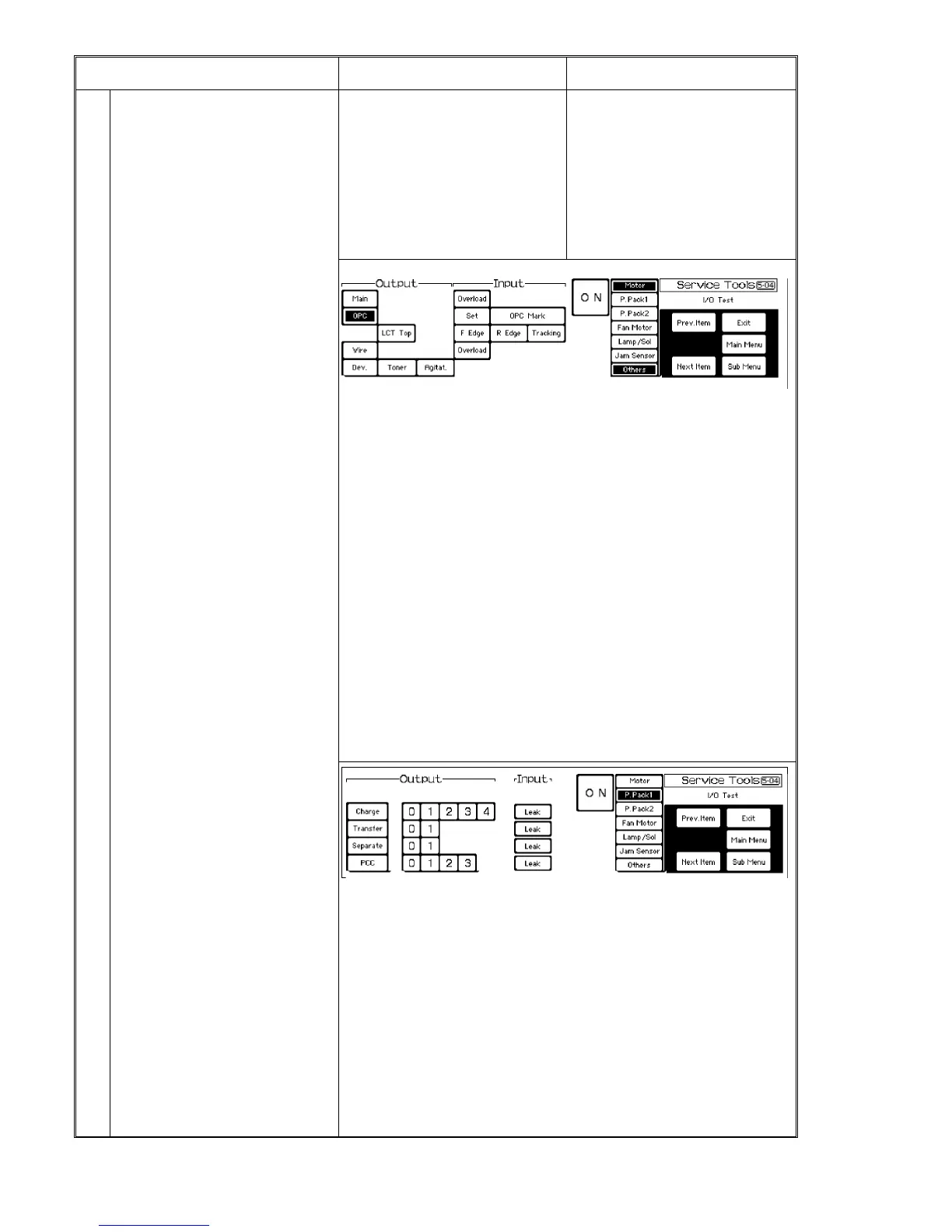
2. Power pack 1
* Output test items
Select output levels for each item using keys [0] to [4].
Charge Charge corona wires
Transfer Transfer corona wire. Standard output level: [0] key ON
Separate Separation corona wire. Standard output level: [0] key ON
PCC PCC wire. Standard output level: [3] key ON
CAUTION:
Turn on the OPC motor for these items to prevent OPC damage.
* Input test items
Press one of the output item keys and its [Leak] key. When leakage occurs, the
buzzer sounds.
1 July 1994 System Test
7-15