2.5.2 Erase mechanism
Light is sent to the charged OPC from the eraser to
erase the electric charge from the non-image areas
(leading and trailing edges, and both sides).
The eraser consists of 186 red LEDs and it controls the
width of light as accurately as possible. The red light
emitted by the LEDs, reduces OPC fatigue.
The erase lighting area is determined by the following
conditions.
• In the ADF or SADF mode, the original size is detected. The original size and magnification ratio are
used to determine the erase lighting area. The whole image may not be copied when an irregular
size original is used in these modes.
• In the platen cover mode, the paper size is used to determine the erase lighting area. In this case,
one more LED each lights at the front and rear as compared with the ADF/SADF mode.
• When the 3-side full image copy mode is selected with user tool [10], two more LEDs each turn off
at the front and rear as compared with the ADF/SADF mode.
• The eraser lights to erase the dummy potential before making the ID sensor pattern. Next, a block
of LEDs turns off to form the electric latent image (420 x 50 mm) for the ID sensor pattern.
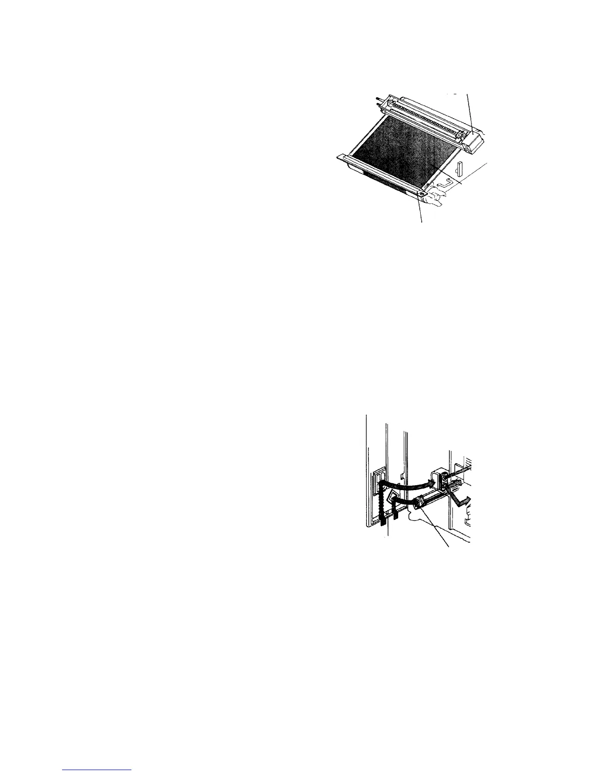
2.5.3 Eraser blower mechanism
To prevent the eraser from becoming dirty, the eraser
blower constantly sends air to the eraser when the main
switch is on.
Charge corona unit
Eraser
OPC
Left front cover
Eraser blower