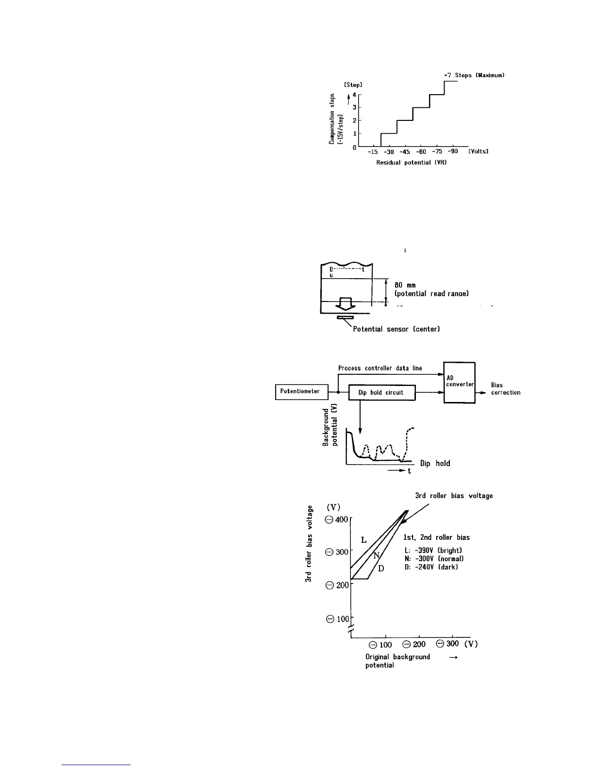
Bias control by process control
The compensation value shown in the figure is added to
the bias voltage based on the residual surface potential
of the OPC.
NOTE
• The maximum compensation value is -105
volts (seven steps in the process control). So,
the maximum bias voltage is -525 volts.
• The same compensation value is applied for all
development rollers.
• When the residual voltage is between 0 and
22.5 volts, no compensation value is applied.
Bias control in AID mode
Three kinds of voltage output curves are provided
according to the automatic image density (AID) level
selected by user tool [2]. The original on the exposure
glass is exposed on the OPC and the potential of a
certain area (see figure) is measured by the potential
sensor. The bias voltage corresponding to the
measured potential is applied to the 3rd development
roller. For the 1st and 2nd rollers, -390, -300, or -240
volts are applied according to the selected AID level.
CAUTION
If the ADF is open and copies are made (to make
solid black copies) in the AID mode, the
maximum development bias will be applied.
Avoid this to prevent bias leakage. Use the
manual image density mode to make solid black
copies.
Bias voltage at ID sensor pattern production
When the ID sensor pattern is produced, the image is
developed with the 4th level of the image density keys.
However, compensation by the processing control is
added.
OPC
Original Background
OPC position meets the original leading edge
Potential Controller Data Line