The inversion mode timing chart shows the operation of
each electrical component in the inverter section of the
finisher when 2 A4 copies are made in continuous
operation.
*1
The finisher ON signal is generated from the copier
when the copier main motor starts turning after the Start
key is pressed. The stopper drive motor starts moving
the inverter stopper plate to the position specified by
each paper size.
*2
Just before the paper enters the inverter tray, the speed
of the inverter transport motor is reduced. (The speed
change timing varies according to paper size.) This is to
have the leading edge of the paper hit against the paper
stoppers gently.
*3
Just when the paper leading edge hits the paper
stoppers, the stopper drive motor starts turning to move
the paper upward. Then soon the motor turns in the
opposite direction to return the inverter stopper plate to
the position specified by the paper size.
When the finisher ON signal turns off, the stopper drive
motor turns to return the inverter stopper plate to its
home position.
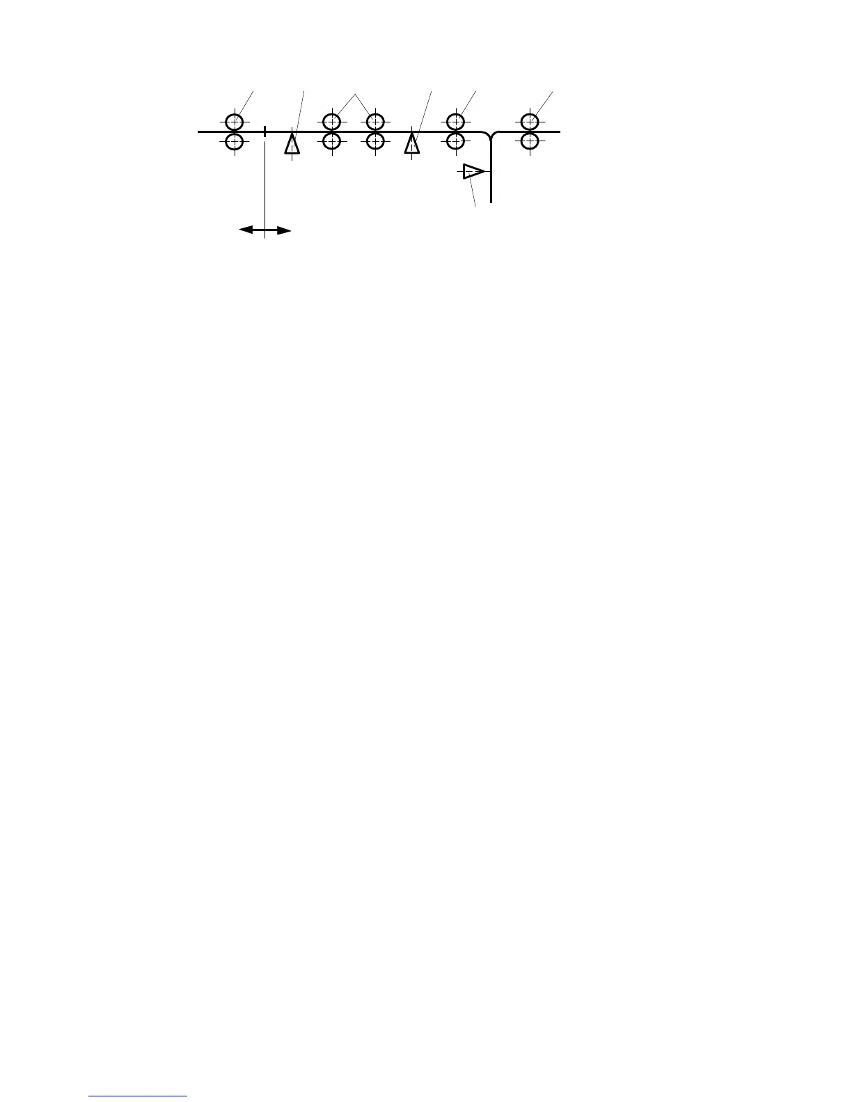
To Finisher
Copier
Inverter
[A] [B] [C]
[D]
[E]
[F]
[G]
[E]: Inverter Guide Roller (In)
[F]: Inverter 3rd Sensor
[G]: Inverter Guide Roller (Out)
[A]: Copier Exit Rollers
[B]: Inverter Entrance Sensor
[C]: Inverter Entrance Rollers
[D]: Inverter 2nd Sensor