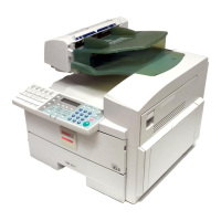
11. Put the two leveling shoes (accessories) under the
stands.
12. From the front and rear, check the clearance
between the exterior covers of the finisher and
copier (or LCT). It must be 3 to 7 mm. To adjust
the position of the finisher with the copier (or LCT),
turn the stand’s nuts as shown.
13. From the top of the finisher, check the position of
the finisher with the copier (or LCT). The finisher
must be aligned with the copier (or LCT) as shown
in the upper illustration. Adjust the finisher height
by turning the stand’s nuts again, if necessary.
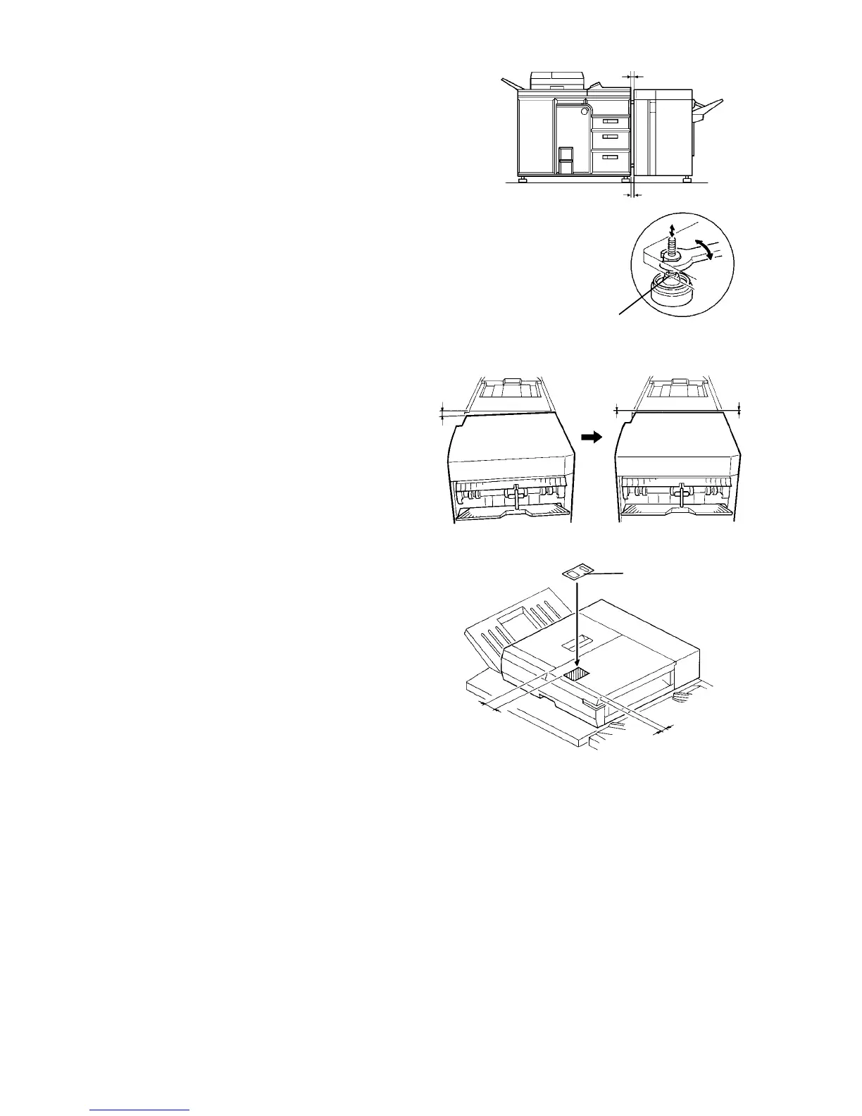
14. Stick the original set position decal (accessory) on
the RDH as shown.
15. Plug the power cord and turn on the main switch of
the copier. Wait for the copy stand-by condition.
16. Access service tool [1-08] and set the finisher
function.
17. Test the operation of the finisher.
NOTE:
• Select the staple mode (2 staple mode) and
make more than 10 sets of copies before start-
ing the stapling operation test. This is because
the staple unit performs stapling motion without
staples until the first staple from the cartridge
reaches the proper position for stapling. This
procedure is required only after installing the
first staple cartridge.
• If customer prefer the shift tray rise mode,
which is to rise the shift tray when the paper on
the tray is removed during a copy run, turn on
dip switch 101-1 on the finisher control PCB.
0 ± 1 mm
0 ± 1 mm
100 mm
10 mm
Decal
5 ± 2 mm
Leveling shoe
5 ± 2 mm