2.2.8 Checking the flash power supply output
1. Remove the clear cover from the flash power
supply unit.
2. Connect the Beckman multimeter between J1(+)
and J2(-). (Range: 20V)
3. Access service tool [5-04], input/output test.
4. Select Lamp/Sol menu and press Charge key.
5. It is normal if the 1/1,000 value of the lamp output
can be read according to the combination of bits
[0][1][2][3][4] as follows:
* About 1.07V with [0] to [4] all OFF
* About 2.00V with [0] to [4] all ON (full power)
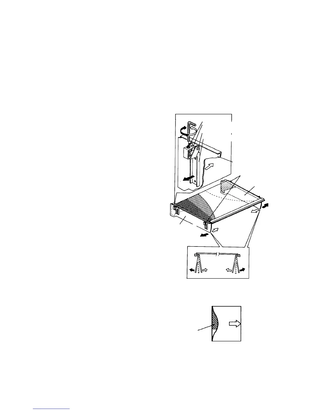
2.2.9 Adjusting the uneven illuminance
CAUTION
This adjustment is usually prohibited.
It seems difficult to return the illuminance to the
original setting if you change the position of the
front and rear reflectors.
1. Use graph paper of A3 size as the original.
2. Copy at the second level of the image density.
3. Check uneven illuminance and make adjustment
with front and rear reflectors.
CAUTION
At this time, set the whole density to the dark
part at the trailing edge of the copy image.
4. After the adjustment, access service tool [4-03]
and check the AID reference voltage using the
PC-1 chart. Perform setting A if the value is not
correct.
CAUTION
When you cannot set the V L target data in the
[4-01] screen due to too low value of the V L
measured data, light quantity to the pattern may
be too high. Therefore, adjust illuminance
again to lower the light quantity to the pattern.
Hex socket screw
Reflector adjusting nut
Rear reflector
Front reflector
Reflector adjustment shaft
Reflector adjustment bracket
Reflector
Reflector
adjusting
mechanism
CAUTION
Never work near the xenon lamp after the flash power
is charged. Be sure to discharge it using the
Discharge key ("Dis" key) in the service tool screen.
Set the whole to
this density



 To Next Page