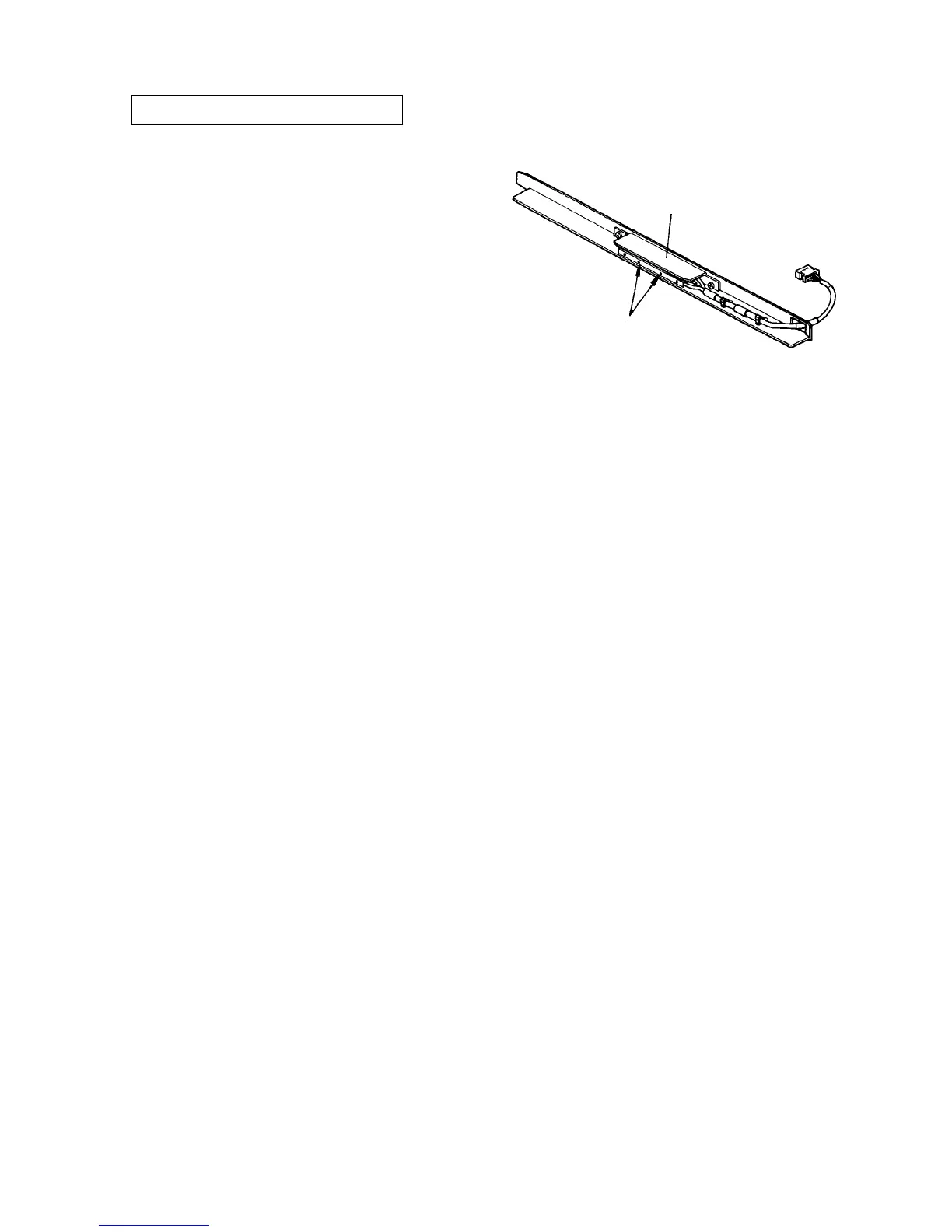
2.4.2 Cleaning the eraser and potential sensor
PM cycle: Clean every 200K
1. Turn off the main switch. Open the front door, and
remove two screws to allow it to open further.
2. Remove the inner cover (2 screws and one
connector)
3. Disconnect a connector from the eraser blower.
4. Remove one screw to remove the eraser blower.
5. Pull out the eraser and wipe it off with a damp
cloth.
6. Pull the sensor connector out of the potential
control board.
7. Pull out the potential sensor and clean it.
CAUTION
Blow air to remove toner and dust from the
electrode. To prevent clogging or jamming, do
not use a rag.
8. Assemble in the reverse order of disassembly.
NOTE
The copy image density may change slightly after
the potential sensor is replaced because the read
potential value may differ slightly from the old
sensor. Check data in the [4-02] screen after
replacing it.
2.4.3 Checking the potential sensor
1. In the copy stand-by condition, measure the voltage between TP6 and TP1 (Ground) on the
interface board. If it is between 1.99 and 2.01 volts, the sensor B is normal. (If the sensor is
defective, it will be 7 to 9 volts or 0 volt.)
2. To turn on the sensor A, short connector CP2-2 and CP2-3 (Ground) on the potential control
board. Otherwise, select "Lamp/Sol" in service tool [5-04] and press "VD Sensor" key. Fol-
low the same procedure as the above to check the sensor A.
Potential sensor
Clear by blowing air



 To Next Page