RIGOL Chapter 5 To Trigger the Oscilloscope
5-38 MSO7000/DS7000 User Guide
➢ Press Bytes, then rotate the multifunction knob or use the pop-up
numeric keypad to set the length of the data. Its range is from 1 to 5.
➢ Press More → Addr Bits, and rotate the multifunction knob to select
the desired address bits. Then press down the knob to select it. You can
also press Addr Bits continuously or enable the touch screen to select it.
The available address bits are "7 Bits", "8 Bits", and "10 Bits".
⚫ A&D: the oscilloscope searches for the specified address and data at the same
time, then triggers when both the address and data meet the conditions. After
this trigger condition is selected, you need to set Bit X, Bytes, Addr Bits,
Address, and Direction menu items. For setting methods, refer to descriptions
in "Address" and "Data" trigger conditions.
Trigger Mode:
In the trigger control area (Trigger) on the front panel, press Mode to quickly switch
the current trigger mode. For details, refer to descriptions in "Trigger Mode".
Trigger Parameter Setting:
Set the trigger parameter (noise rejection) under this trigger type. For details, refer
to descriptions in "Noise Rejection".
Trigger LEVEL/Threshold Level:
Rotate the Trigger LEVEL knob to adjust the trigger level/threshold level. Refer
to "Trigger LEVEL/Threshold Level". The current trigger level/threshold level
value is displayed at the upper-right corner of the screen.
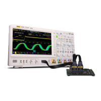
SPI Trigger (Option)
In SPI trigger, after the CS or timeout condition is satisfied, the oscilloscope triggers
when the specified data is found. When using SPI trigger, you need to specify the
SCL clock sources and SDA data sources. Below is the sequential chart of SPI bus.