Chapter 11 Protocol Decoding RIGOL
MSO7000/DS7000 User Guide 11-19
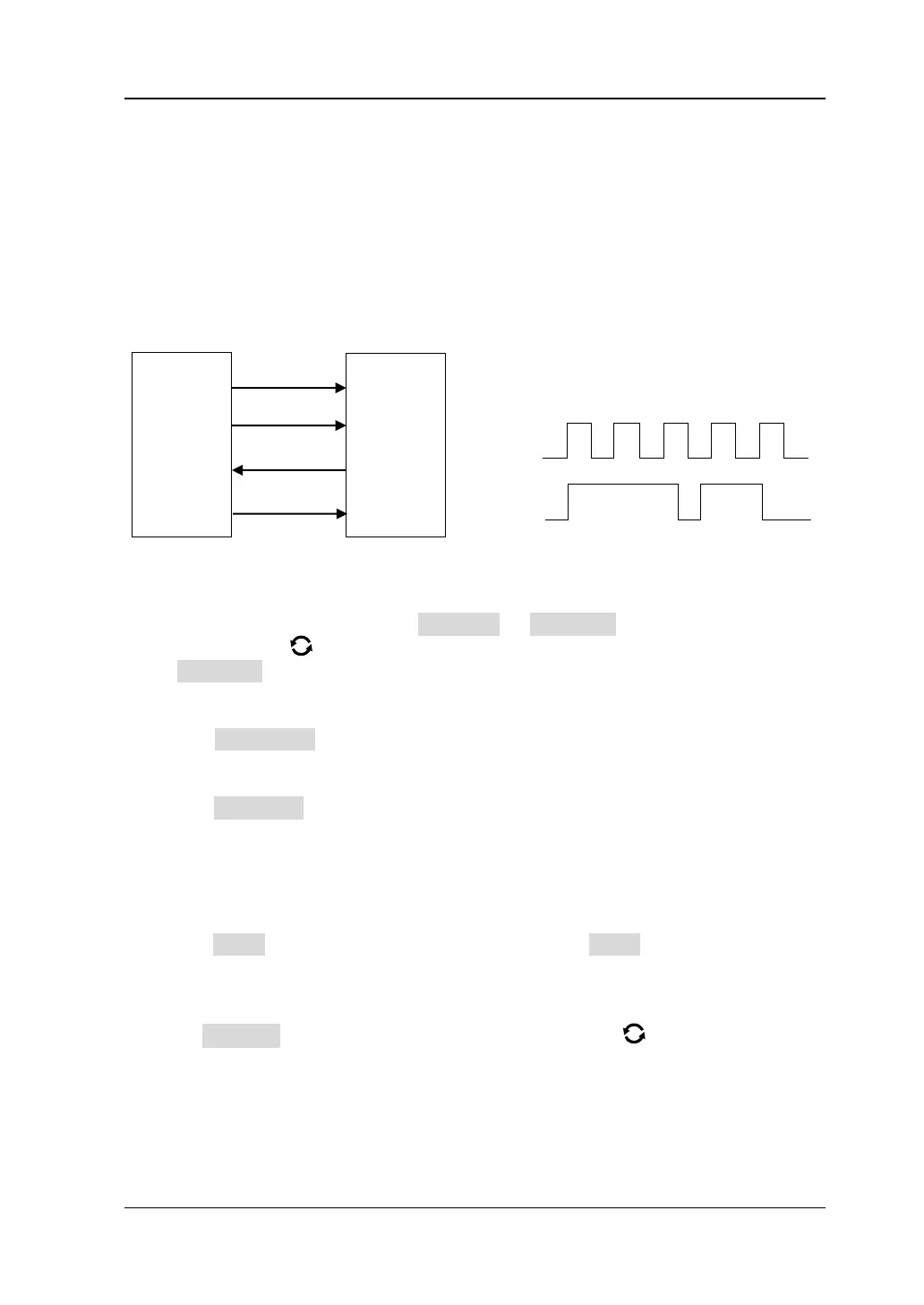
SPI Decoding (Option)
SPI bus is based on the master-slave configuration and usually consists of chip select
line (CS), clock line (CLK), and data line (SDA). Wherein, the data lines include the
master input/slave output (MISO) data line and master output/slave input (MOSI)
data line. The oscilloscope samples the channel data on the rising or falling edge of
the clock signal (if the source is an analog channel, the oscilloscope will also judge
each data point (logic "1" or logic "0") according to the preset threshold level).
Figure 11-7 SPI Serial Bus
In the decode setting menu, press Decode1 → Bus Type, then rotate the
multifunction knob to select "SPI". Press down the knob to select it. You can also
press Bus Type continuously or enable the touch screen to select it.
1. Enable or disable the bus
Press Bus Status to enable or disable the decoding function.
2. Quickly apply SPI trigger settings to SPI decoding
Press Copy Trig to copy the SPI trigger settings and apply them to SPI
decoding function (set the corresponding SPI decoding parameters
automatically). For analog channels, the threshold level settings will also be
copied.
3. Mode
Press Mode to enter the mode setting menu. Press Mode continuously to select
"Timeout" or "CS".
⚫ Timeout: you can perform frame synchronization according to the timeout,
and the timeout value must be greater than half of the clock cycle. Press
Timeout, and then rotate the multifunction knob or use the pop-up
numeric keypad to set the timeout value. The available range of the timeout
value is from 8 ns to 10 s. By default, it is 1 μs.
⚫ CS: contains a chip select line (CS). You can perform frame synchronization
according to CS. When "CS" is selected,