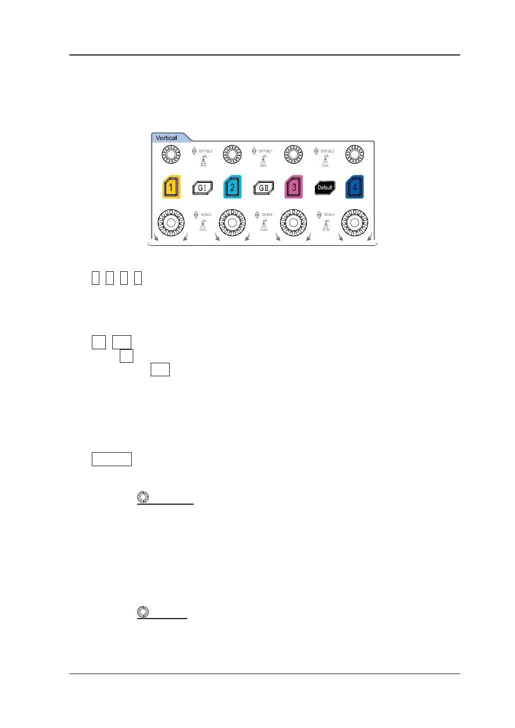
⚫ 1, 2, 3, 4: indicates the analog channel switch key. The four channels are
marked by different colors which are also used to mark both the corresponding
waveforms of the specified channel on the screen and the channel input
connectors.
⚫ GI, GII: indicates the Function/Arbitrary Waveform Generator setting key.
Press GI to enable or disable the output of the [GI] connector on the front
panel; press GII to enable or disable the output of the [GII] connector on the
front panel; and then enter the corresponding Function/Arbitrary Waveform
Generator setting interface. Enable or disable the status display of the current
signal.
Note: This function is only available for the MSO7000 model installed with the
Function/Arbitrary Waveform Generator option.
⚫ Default: indicates the default setting key. Press this key to restore the
instrument to its factory default settings.
⚫ Vertical OFFSET: indicates the channel vertical offset knob. You can
rotate the knob to modify the vertical offset of the current channel waveform.
Each analog channel is configured with an independent vertical offset
adjustment knob. Turn it clockwise to increase the offset, and turn it
counterclockwise to decrease the offset. During the modification, the waveform
would move up and down. Meanwhile, the offset information in the
corresponding status label would change accordingly. Press down this knob to
quickly reset the vertical offset to zero.
⚫ Vertical SCALE: indicates the channel vertical scale knob. Modify the
vertical scale of the current channel. Each analog channel is configured with an
independent vertical scale adjustment knob. Turn it clockwise to decrease the