20 Rockwell Automation Publication 1426-UM001J-EN-P - August 2019
Chapter 2 Install the PowerMonitor 5000 Unit
Voltage Sensing
Circuits that are rated up to 690V AC line-to-line can be connected directly.
Higher voltages require potential transformers (PTs), also known as voltage
transformers (VTs), to step the voltage down.
Wiring must conform to all applicable codes and standards. In particular, you
provide suitable overcurrent protection, with current and interrupting ratings
that are selected to help protect the wiring.
Pay particular attention to correct phasing and polarity of voltage connections.
The diagrams use the ‘dot’ convention to indicate transformer polarity. The dot
indicates the H1 and X1 terminals on the high side and low side of the
transformer respectively.
When wiring a PowerMonitor 5000 unit to existing PTs and metering devices,
connect the voltage sensing terminals of the PowerMonitor 5000 unit in parallel
with the voltage sensing terminals of the existing metering devices.
The following wiring diagrams indicate typical voltage sensing connections to
various types of power systems.
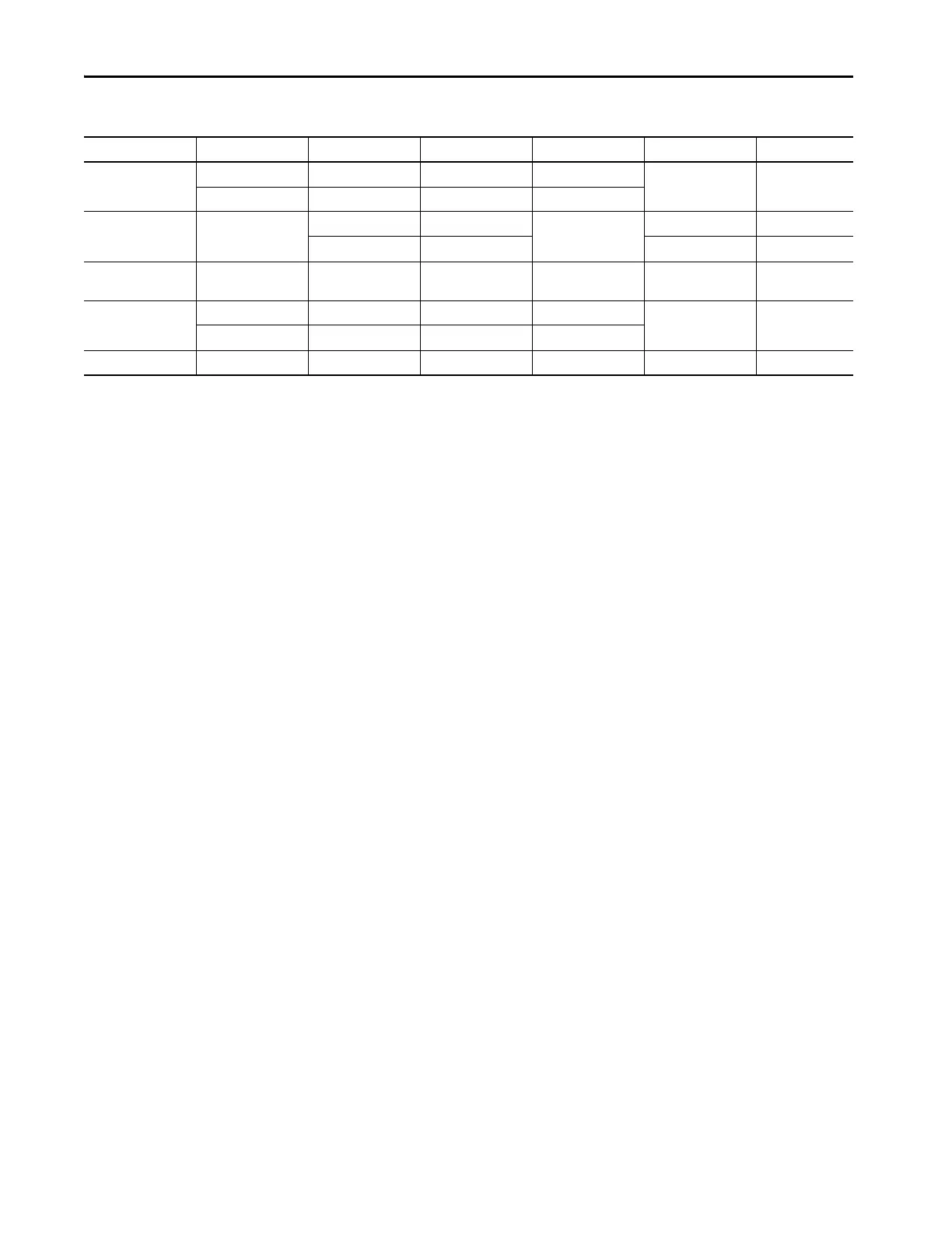
Split-phase ≤690V 2/1 - Diagram V7 Diagram I1 Split-phase
> 690V 2/1 2/1 Diagram V8
3-phase, 3-wire delta,
Grounded B Phase
(1)
≤690V 2 - Diagram V9 Diagram I2 Delta Grd B Ph 2 CT
3 - Diagram I3 Delta Grd B Ph 3 CT
3-phase, 4-wire high
leg
(1)
(wildcat)
≤690V 3 - Diagram V10 Diagram I3 Delta high leg
Single phase ≤690V 1 - Diagram V11 Diagram I4 Single phase
> 690V 1 1 Diagram V12
For demo use-----Demo
(1) Delta Grounded B Phase and delta high leg are not supported above 690V L-L. Use the 3-phase, 3-wire delta circuit type.
(2) 2 PTs used in open-delta configuration.
Table 5 - Selecting Wiring Diagrams and Metering Modes (continued)
Circuit Type Line - Line Voltage No. of CTs No. of PTs Voltage Sensing Current Sensing Metering_Mode

 Loading...

