EasyManuals Logo

Rockwell Automation Allen-Bradley PowerMonitor 5000 Unit User Manual

Rockwell Automation Allen-Bradley PowerMonitor 5000 Unit
514 pages
To Next Page IconTo Next Page
To Previous Page IconTo Previous Page
Page #21 background imageLoading...
Page #21 background image
Rockwell Automation Publication 1426-UM001J-EN-P - August 2019 21
Install the PowerMonitor 5000 Unit Chapter 2
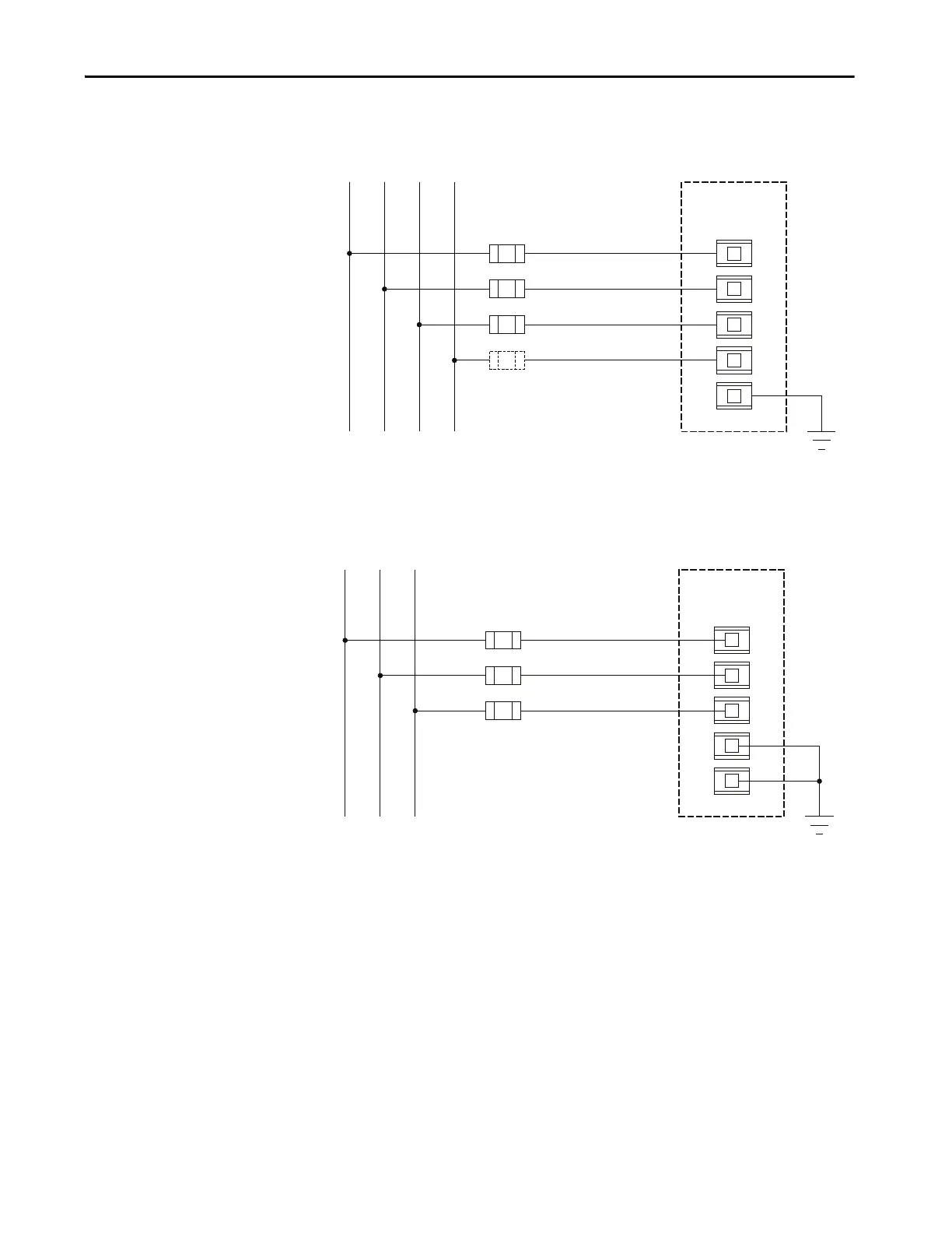
Figure 4 - Diagram V1 - 3-phase, 4-wire Wye (690V AC Line-to-line Maximum)
Figure 5 - Diagram V2 - 3-phase, 3-wire Grounded Wye, or 3-phase, 3-wire Delta (690V AC Line-to-
line Maximum)
Metering_Mode = Wye
V1
V2
VG
V3
VN
PowerMonitor 5000
Fuses (by user)
L1 L2 L3 N
Line
Load
Ground
(1) Fuse in neutral connection is required for impedance grounded systems.
(1)
V1
V2
VG
V3
VN
Metering_Mode = Wye,
Delta 2 CT or Delta 3 CT,
as applicable
PowerMonitor 5000
Fuses (by user)
L1 L2 L3
Line
Load
Ground

Table of Contents

Questions and Answers:

Question and Answer IconNeed help?

Do you have a question about the Rockwell Automation Allen-Bradley PowerMonitor 5000 Unit and is the answer not in the manual?

Rockwell Automation Allen-Bradley PowerMonitor 5000 Unit Specifications

General IconGeneral
BrandRockwell Automation
ModelAllen-Bradley PowerMonitor 5000 Unit
CategoryIndustrial Equipment
LanguageEnglish

Related product manuals