5
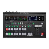
Panel Descriptions
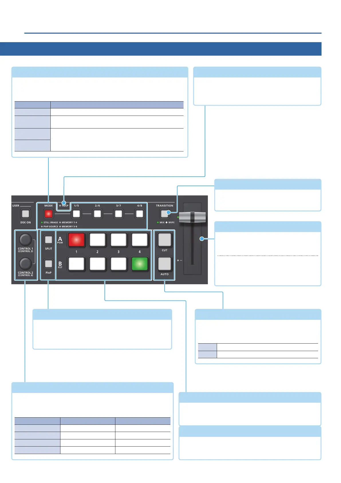
Top Panel
A/PGM cross-point [1]–[4] buttons
Selects the video to input to bus A/PGM. The selected
button lights up.
Video fader
(p. 14, 15)
Manually switch between the videos being
input to bus A/PGM and B/PST, and send
them to the nal output.
Transition indicators
The indicator for the nal output bus and
lights up.
[SPLIT] [PinP] buttons
(p. 24, 25, 26)
Turns on/o video compositing using split or PinP
(picture-in-picture).
When turned on, the [SPLIT] or [PinP] button is lit.
B/PST cross-point [1]–[4] buttons
Selects the video to input to bus B/PST. The selected button
lights up.
[CONTROL 1] [CONTROL 2] knobs
(p. 24, 25, 26)
Adjust the split or PinP compositing settings.
If you turn a knob while pressing it, these knobs function as
[CONTROL 3] [CONTROL 4] knobs.
Knob Split PinP
[CONTROL 1] A-CENTER POSITION H
[CONTROL 2] B-CENTER POSITION V
[CONTROL 3] CENTER POSITION SIZE
[CONTROL 4] SPLIT TYPE ZOOM
[CUT] [AUTO] buttons
(p. 14, 15, 17)
Automatically switch between the videos being
input to bus A/PGM and B/PST, and send them to the
nal output.
[CUT] The video switches instantly.
[AUTO] The video switches with a transition eect applied.
HDCP indicator
(p. 13)
This indicator is lit, blinking, or unlit according to the
HDCP (copy protection) setting and according to
whether an HDCP-compliant device is connected.
[MODE] button, [1/5]–[4/8] buttons
Use the [MODE] button to select the function of the [1/5]–[4/8] buttons.
An indicator located below the [MODE] button is lit to indicate the current
function.
Indicator Function
STILL IMAGE Output a still image (p. 22).
PinP SOURCE
When using PinP compositing, select the video source for the
inset screen (p. 25, 26).
MEMORY 1–4
Recall the settings saved in a preset memory (1–8).
Long-press a button to save the current settings in a preset
memory (p. 38).
MEMORY 5–8
[TRANSITION] button
(p. 14, 15, 16)
Selects the video transition eects (MIX,
WIPE).