67
Appendices
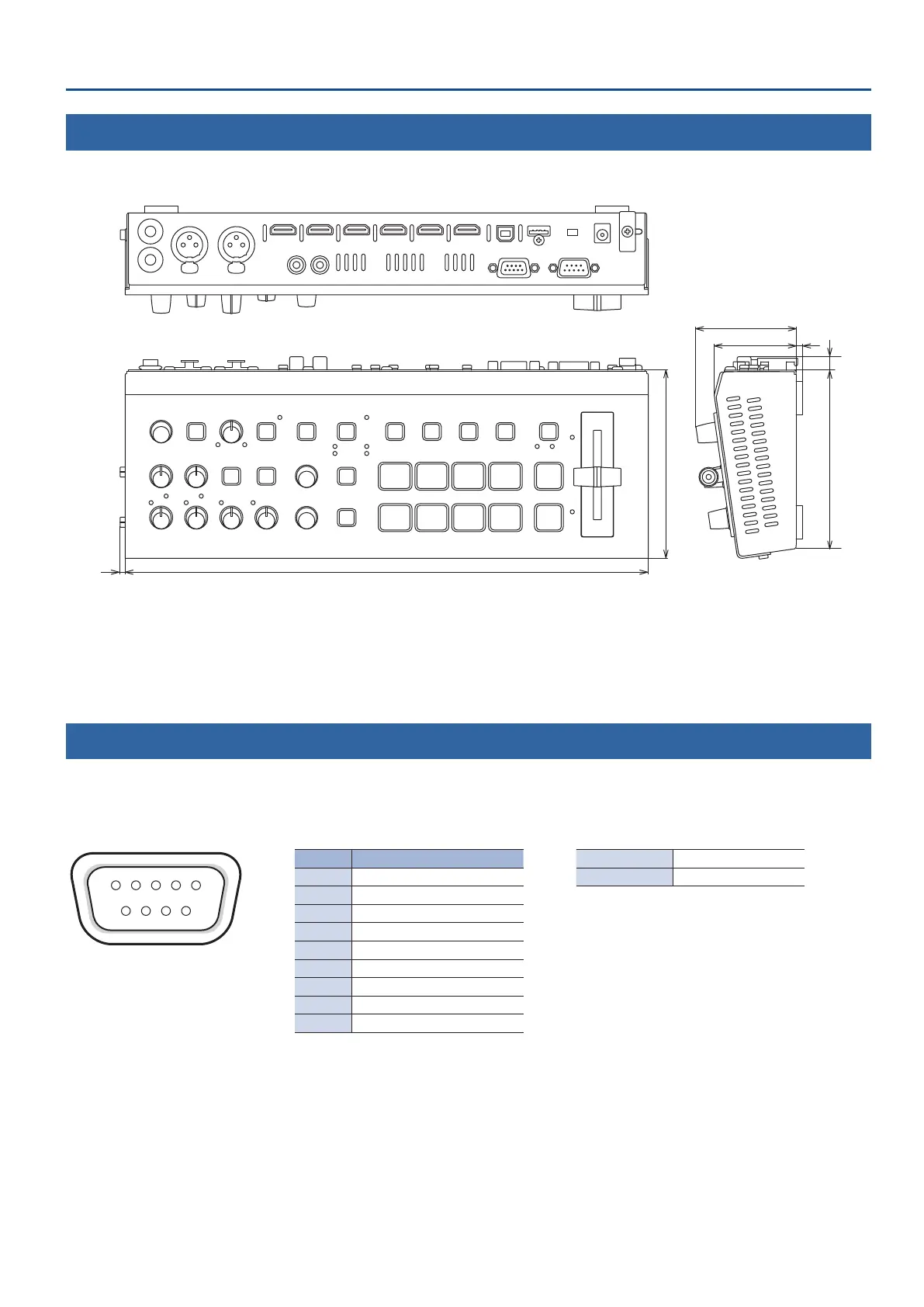
Dimensions
61
49 4
113
107
3133
8
Unit: mm
Specication of the TALLY Connector
A tally signal can be output from the connector pin that supports nal output video and preview output video.
* To output the tally signal, press the [MENU] button, and from “TALLY/RS-232,” set “TALLY” to “ON.”
TALLY connector pin layout Pin assignments Tally output
5 4 3 2 1
9 8 7 6
DB-9 type (female)
Pin No. Target Trigger method Open collector
1 GND Maximum input 12 V/200 mA
2 PGM/A cross-point [1] button
3 PGM/A cross-point [2] button
4 PGM/A cross-point [3] button
5 PGM/A cross-point [4] button
6 PST/B cross-point [1] button
7 PST/B cross-point [2] button
8 PST/B cross-point [3] button
9 PST/B cross-point [4] button