Reference Manual
00809-0100-4360, Rev BA
August 2008
2-17
Rosemount 1151
Grounding Effects
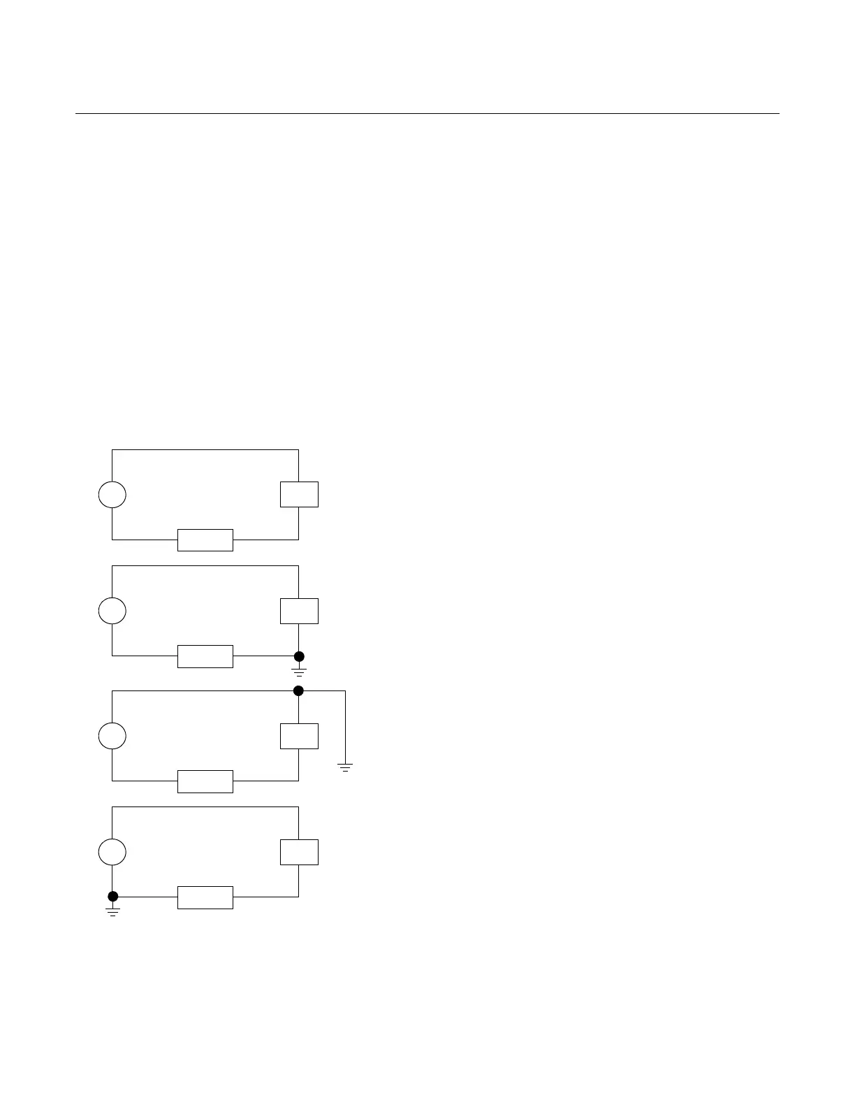
The capacitance sensing module requires alternating current to generate a
capacitance signal. This alternating current is developed in an oscillator circuit
with a frequency of approximately 32 kHz. This signal is capacitor-coupled to
transmitter-case ground through the sensing module. Because of this
coupling, a voltage may be imposed across the load, depending on the choice
of grounding. See Figure 2-9.
Impressed voltage, which is seen as high frequency noise, will have no effect
on most instruments. Computers with short sampling times in circuits will
detect a significant noise signal, which should be filtered out by using a large
capacitor (1 μF) or by using a 32 kHz LC filter across the load. Computers that
are wired and grounded, as shown in Figure 2-9, are negligibly affected by
this noise and do not need filtering.
Figure 2-9. Effects of Grounding
on Accuracy for Fast Sample
Computers.
PT
LOAD
PS
+
–
Ungrounded System
Impressed Voltage: 12 to 22 mV
p-p
32 kHz
Effect: 0.01% of span, max.
PT
LOAD
PS
+
–
PT
LOAD
PS
+
–
PT
LOAD
PS
+
–
Ground Between Negative Side of Power Supply and Load
Impressed Voltage: 35 to 60 mVp-p
32 kHz
Effect: 0.03% of span, max.
Ground Between Positive Side of Transmitter and Power Supply
Impressed Voltage: 35 to 60 mVp-p
32 kHz
Effect: 0.03% of span, max.
Ground Between Negative Terminal of Transmitter and Load
Impressed Voltage: 500 to 600 mVp-p
32 kHz
Effect: 0.27% of span, max.
*The effect caused by the impressed voltage on a computer with a sampling time
of 100 microseconds using a 2 to 10 volt signal.