Reference Manual
00809-0100-4360, Rev BA
August 2008
Rosemount 1151
3-2
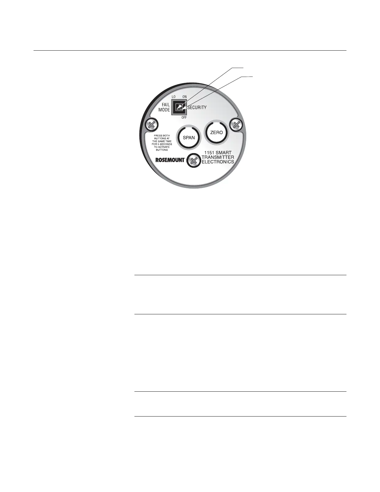
Failure Mode Alarm Switch
As part of its normal operation, the Rosemount 1151 Smart continuously
monitors its own operation. This automatic diagnostic routine is a timed series
of checks repeated continuously.
The electronics faceplate has HI and LO user-selectable failure mode
settings, refer to Figure 3-1. If the diagnostic routine detects a failure in the
transmitter in analog output, the transmitter either drives its output below 3.8
mA or above 21.0 mA, depending on the position of the failure mode alarm
switch.
NOTE
With multidrop (digital) output, the analog output remains at 4 mA, even when
a diagnostic failure is detected. This is true for both the HI and LO fail mode
switch settings. A bit is enabled in the digital word to indicate a diagnostic
failure.
Transmitter Security (Write-Protection Switch)
Once the transmitter has been configured, it may be desirable to protect the
configuration data from changes. The electronics assembly is equipped with a
switch labeled SECURITY. Figure 3-1 shows the switch location on the circuit
side of the electronics housing. In the ON position, the switch prevents the
accidental or deliberate change of configuration data. To enable the sending
of configuration data, simply return the transmitter security switch to the OFF
position.
NOTE
The transmitter security switch must be in the OFF position before
configuration changes can be made to the transmitter configuration.
NOTE
User-selectable switches are
shown in default position
Figure 3-1.
Transmitter Switch Locations.
Transmitter Security Switch
Fail Safe Mode Switch