94
Reference Manual
00809-0100-4803, Rev GA
Operation and Maintenance
September 2017
Operation and Maintenance
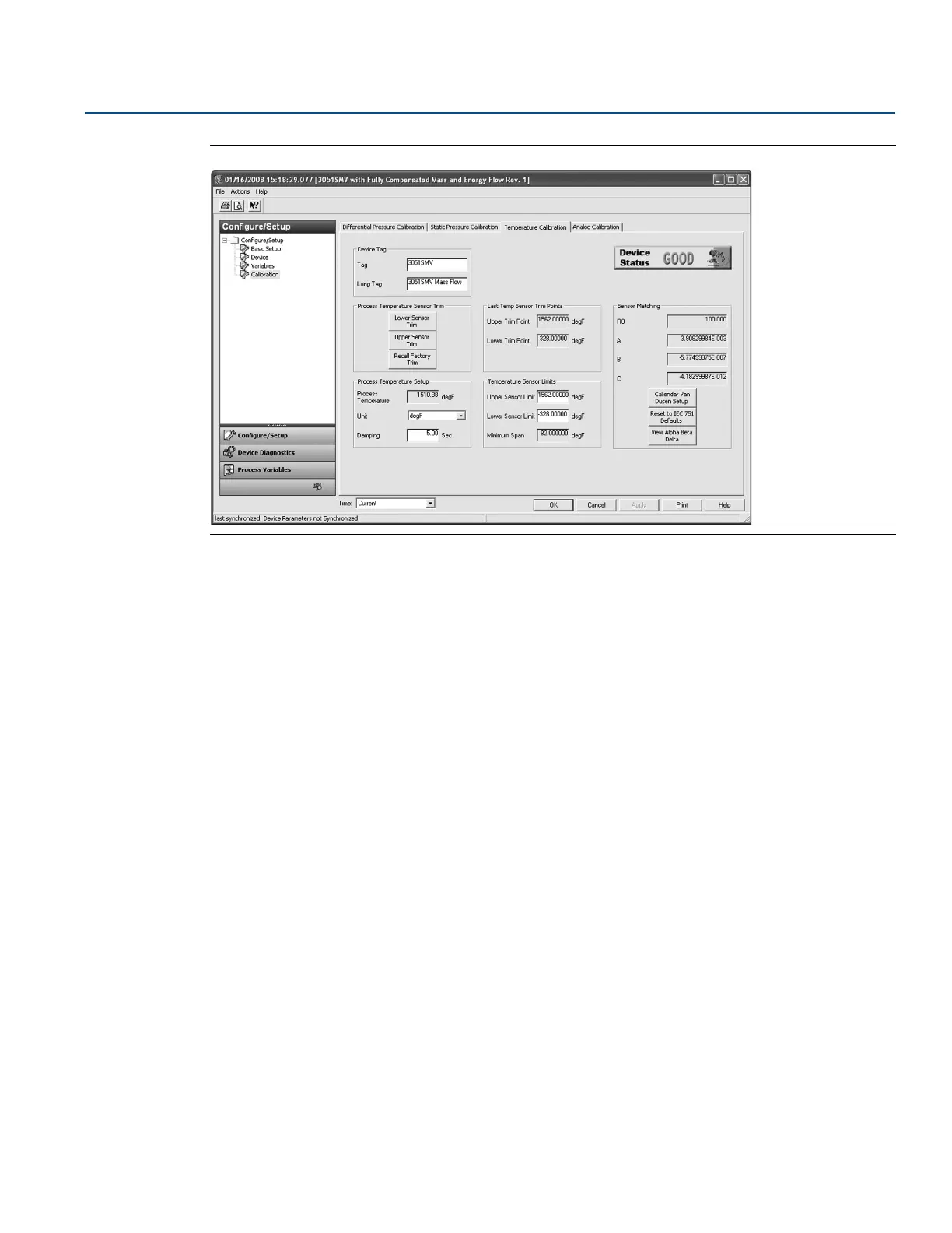
Figure 4-4. Calibration - Temperature Calibration Tab
Process temperature upper and lower sensor trim
To calibrate the Process Temperature Input using the sensor trim, follow the procedure shown below:
1. Set up a Temperature Calibrator to simulate a Pt 100 (100-ohm platinum, alpha 385 RTD). Wire the
two red wires from the Rosemount 3051SMV terminal block to one connection, and the two white
wires to the other connection. See “Install optional process temperature input (Pt 100 RTD sensor)”
on page 76 for more information.
2. Adjust the calibrator/RTD simulator to a test point temperature value that represents a minimum
process temperature (for example, 32 °F or 0 °C). Select the Lower Sensor Trim button under the
Process Temperature Sensor Trim heading and follow the on-screen prompts.
3. Adjust the calibrator/RTD simulator to a test point temperature value that represents the maximum
process temperature (for example, 140 °F or 60 °C). Select the Upper Sensor Trim button under the
Process Temperature Sensor Trim heading and follow the on-screen prompts.
Recall factory trim
The Recall Factory Trim button will restore the transmitter to the original factory calibration settings.
When the recall factory trim function is used, the transmitter’s upper and lower trim values are set to the
values configured at the factory. If custom trim values were specified when the transmitter was ordered,
the device will recall those values. If custom trim values were not specified, the device will recall the
upper and lower sensor limits.
Transmitter RTD sensor matching using Callendar-Van Dusen
constants
The Rosemount 3051SMV accepts Callendar-Van Dusen constants from a calibrated RTD schedule and
generates a special custom curve to match that specific sensor Resistance vs. Temperature performance.
Matching the specific sensor curve with the transmitter configuration enhances the temperature
measurement accuracy.
 Loading...


