35
Reference Manual
00809-0100-4803, Rev GA
Configuration
September 2017
Configuration
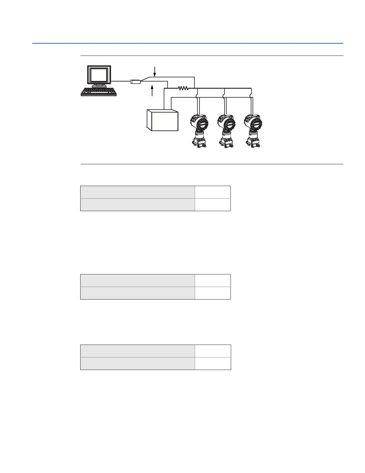
Figure 2-24. Typical Multidrop Network
A. Power supply
B. HART modem
Enable multidrop communication
The Rosemount 3051SMV is set to address zero (0) at the factory, which allows operation in the standard
point-to-point manner with a 4–20 mA output signal. To activate multidrop communication, the
transmitter address must be changed to 1–15 for HART 5 hosts or 1–63 for HART 6 hosts. This change
deactivates the 4–20 mA analog output, sending it to a fixed value of 4 mA. It also disables the failure
alarm signal, which is controlled by the HI/LO alarm switch position on the feature board. Failure signals
in multidropped transmitters are communicated through HART messages.
Loop current mode
When using multidrop communication, the loop current mode drop-down menu defines how the 4–20
mA analog output behaves. When loop current mode is disabled, the analog output will be fixed at
4 mA. When the loop current mode is enabled, the analog output will follow the primary variable.
2.6.6 Materials of construction
The Materials of Construction tab allows the materials of construction, remote seal, and equipped sensor
information to be viewed. The parameters shown in white boxes may be edited by the user, but do not
affect the operation of the device.
Mass and energy flow Fast Keys
1, 4, 3, 3, 1
Direct process variable output Fast Keys
1, 4, 3, 3, 1
Mass and energy flow Fast Keys
1, 4, 3, 3, 2
Direct process variable output Fast Keys
1, 4, 3, 3, 2
Mass and energy flow Fast Keys
1, 4, 4, 2
Direct process variable output Fast Keys
1, 4, 4, 2