103
Reference Manual
00809-0100-4803, Rev GA
Operation and Maintenance
September 2017
Operation and Maintenance
4.6.4 LCD display
Transmitters ordered with the LCD display will be shipped with the display installed. Installing the display
on an existing Rosemount 3051SMV requires the LCD display kit (part number 03151-9193-0001 for
aluminum housing and 03151-9193-0004 for stainless steel (SST) housing).
Use the following procedure and Figure 4-13 to install the LCD display:
1. If the transmitter is installed in a loop, then secure the loop and disconnect power.
2. Remove the transmitter cover on the feature board side (opposite the field terminals side). Do not
remove the instrument covers in explosive environments when the circuit is live.
3. Engage the four-pin connector into the feature board and snap the LCD display into place.
4. Install the display cover and tighten to ensure metal to metal contact in order to meet
flameproof/explosion-proof requirements.
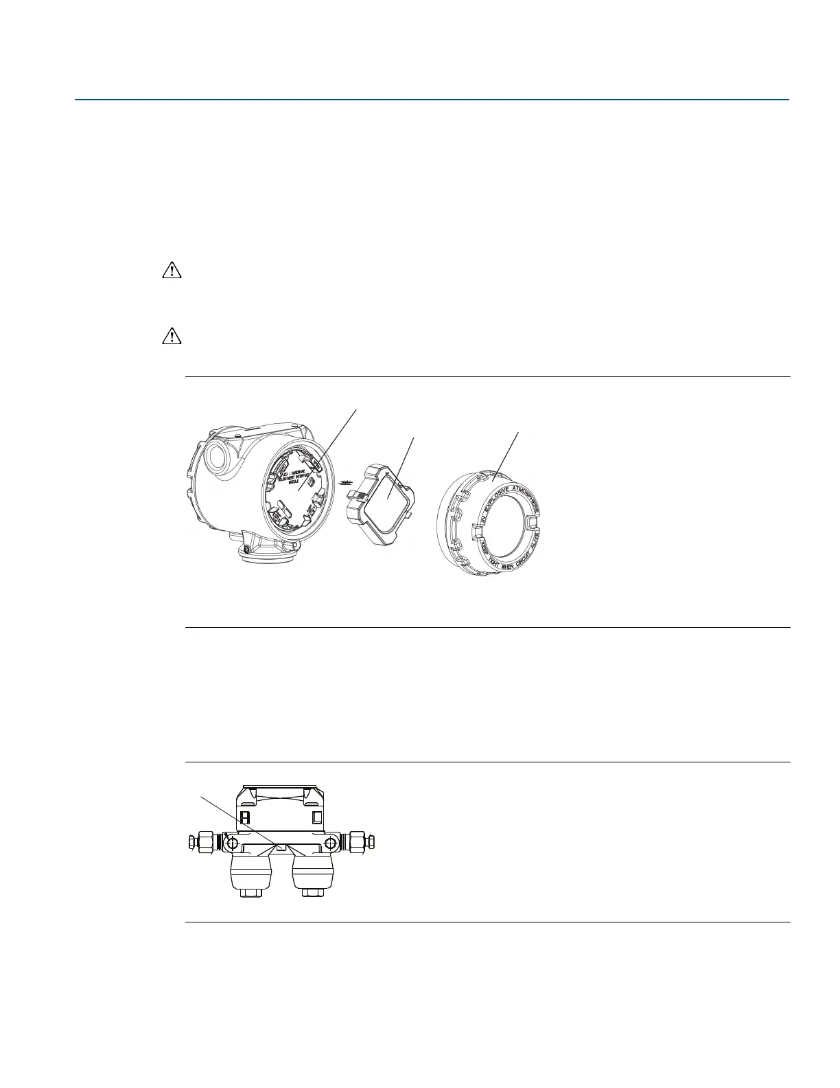
Figure 4-13. Optional LCD Display
A. Feature board
B. LCD display
C. Display cover
4.6.5 Flange and drain vent
The Rosemount 3051SMV is attached to the process connection flange by four bolts and two alignment
cap screws.
1. Remove the two alignment cap screws.
Figure 4-14. Alignment Cap Screws
A. Alignment cap screw
2. Remove the four bolts and separate the transmitter from the process connection, but leave the
process connection flange in place and ready for re-installation.
 Loading...


