62
Reference Manual
00809-0100-4803, Rev GA
Configuration
September 2017
Configuration
2.8.1 Field Communicator Fast Keys
Use Rosemount 3051SMV Engineering Assistant or any HART-compliant master to communicate with
and verify configuration of the Rosemount 3051SMV.
Tab le 2 -1 3 shows the Field Communicator Fast Keys for the fully compensated mass and energy flow.
Table 2-14 on page 63 shows the Fast Keys for the direct process variable output.
A check (⻫) indicates the basic configuration parameters. At a minimum, these parameters should be
verified as part of the configuration and startup procedure.
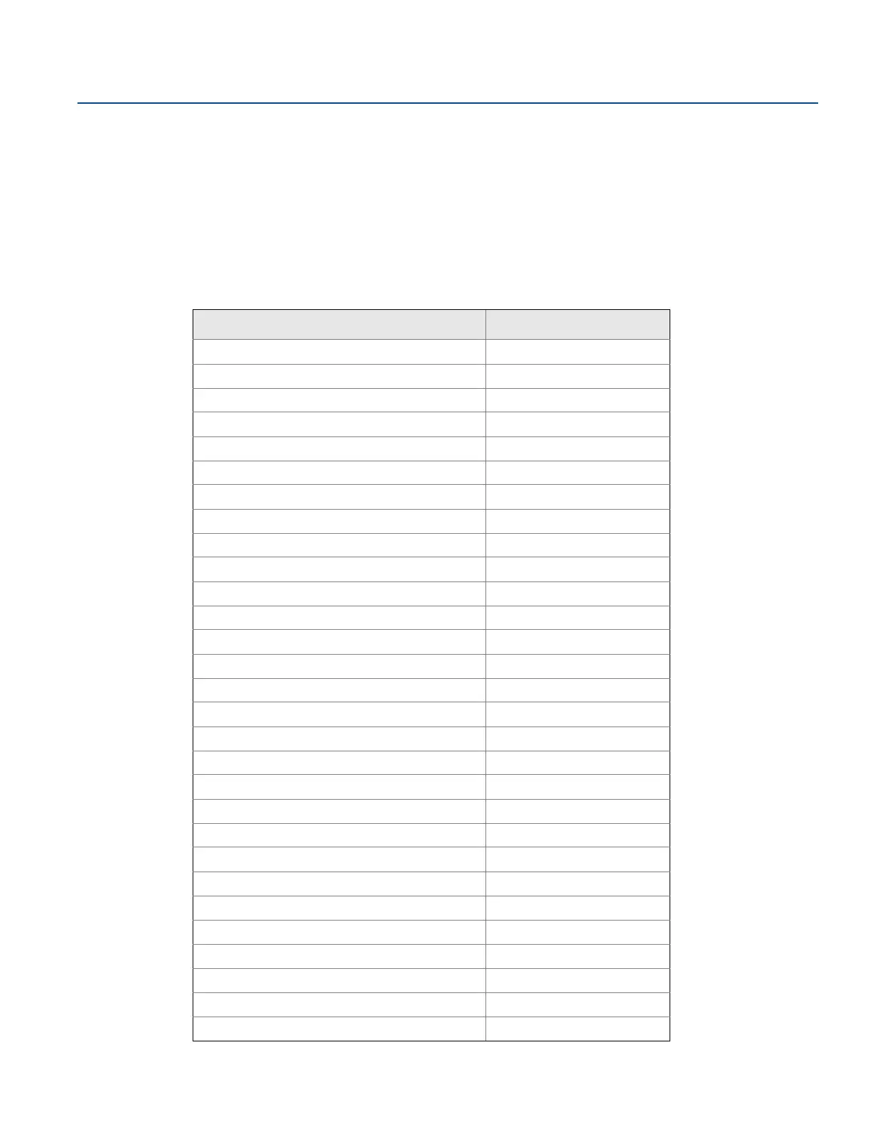
Table 2-13. Fast Keys for Fully Compensated Mass and Energy Flow Output
Function Fast Key sequence
Absolute Pressure Reading and Status 1, 4, 2, 1, 5
Absolute Pressure Sensor Limits 1, 4, 1, 5, 8
Absolute Pressure Units 1, 3, 3, 5
Alarm and Saturation Level Configuration 1, 4, 2, 6, 6
Alarm and Saturation Levels 1, 4, 2, 6
Analog Output Trim Options 1, 2, 5, 2
Burst Mode Setup 1, 4, 3, 3, 3
Burst Mode Options 1, 4, 3, 3, 4
Callendar-van Dusen Sensor Matching 1, 2, 5, 5, 4
Configure Fixed Variables 1, 2, 4
Damping 1, 3, 7
Diaphragm Seals Information 1, 4, 4, 5
⻫
Differential Pressure Low Flow Cutoff 1, 4, 1, 1, 6
Differential Pressure Reading and Status 1, 4, 2, 1, 4
Differential Pressure Sensor Trim Options 1, 2, 5, 3
⻫
Differential Pressure Zero Trim 1, 2, 5, 3, 1
Differential Pressure Units 1, 3, 3, 4
Energy Rate Units 1, 3, 3, 2
Energy Reading and Status 1, 4, 2, 1, 2
Equipped Sensors 1, 4, 4, 4
Field Device Information 1, 4, 4, 1
Flow Calculation Type 1, 4, 1, 1, 2
⻫
Flow Rate Units 1, 3, 3, 1
Flow Reading and Status 1, 4, 2, 1, 1
Gage Pressure Reading and Status 1, 4, 2, 1, 6
Gage Pressure Sensor Limits 1, 4, 1, 5, 9
Gage Pressure Units 1, 3, 3, 6
LCD Display Configuration 1, 3, 8
Loop Test 1, 2, 2