68
Reference Manual
00809-0100-4803, Rev GA
Installation
September 2017
Installation
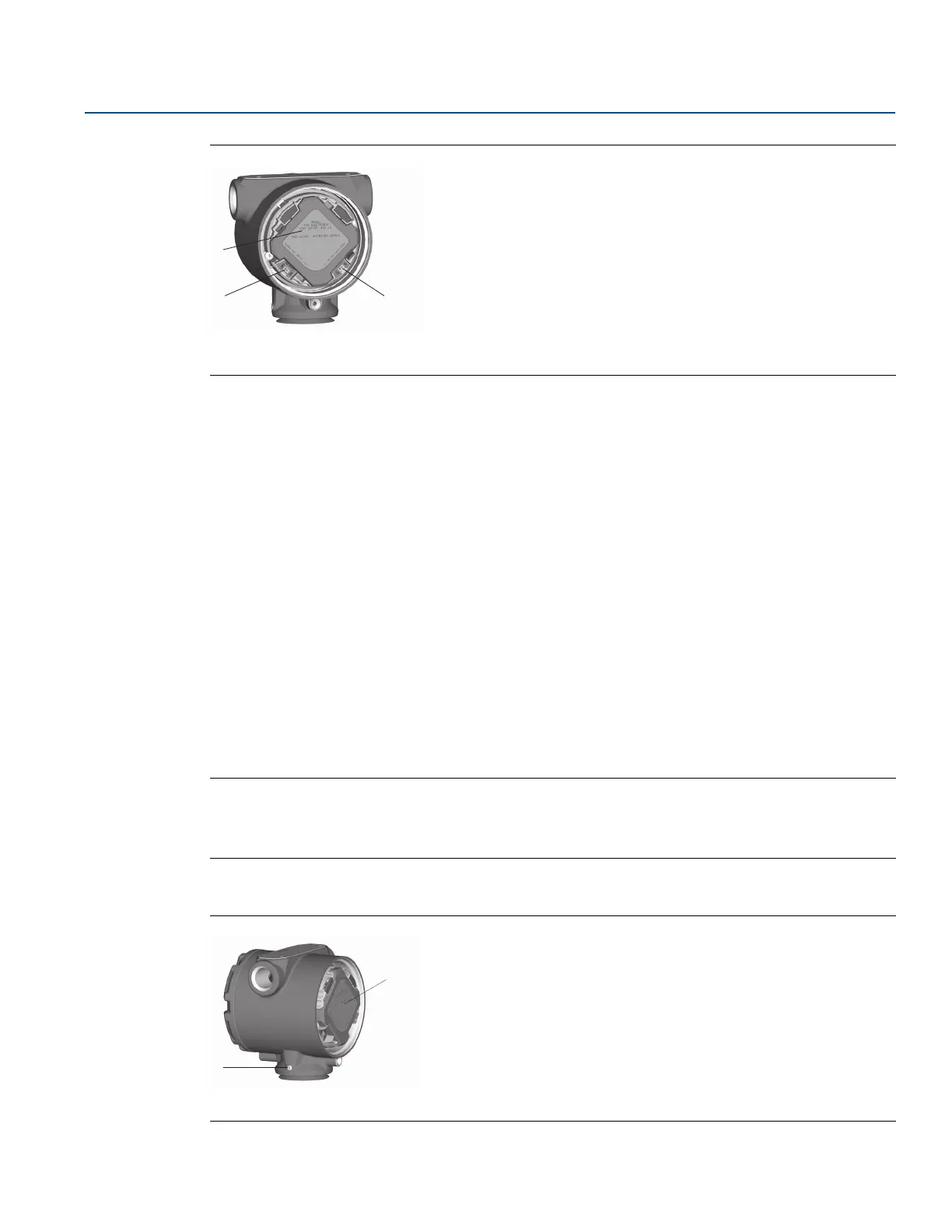
Figure 3-1. Switch Configuration
A. Feature board
B. Security
C. Alarm
4. Re-install the transmitter cover. Transmitter covers must be fully engaged so that metal contacts
metal in order to meet flameproof/explosion-proof requirements.
3.4.2 Configure alarm direction
The transmitter alarm direction is set by repositioning the alarm switch. Position the switch in the HI
position for fail high and in the LO position for fail low. See “Alarm and saturation” on page 27 for more
information on alarm and saturation levels.
3.4.2 Mounting considerations
For dimensional drawing information refer to “Specifications and Reference Data” on page 125.
Housing rotation
The housing can be rotated to improve field access to wiring or to better view the optional LCD display.
To rotate the housing, perform the following procedure:
1. Loosen the housing rotation set screw.
2. Turn the housing up to 180° to the left or right of its original (as shipped) position.
Note
Do not rotate the housing more than 180° without first performing a disassembly procedure (see
“Housing assembly including feature board electronics” on page 100). Over-rotation may sever the
electrical connection between the sensor module and the feature board.
3. Retighten the housing rotation set screw.
Figure 3-2. Housing
A. Feature board
B.
3
/32-in. housing rotation set screw