95
Reference Manual
00809-0100-4803, Rev GA
Operation and Maintenance
September 2017
Operation and Maintenance
Under the Sensor Matching heading, the Callendar-Van Dusen constants R
0
, A, B, and C can be viewed. If
the Callendar-Van Dusen constants are known for the user’s specific Pt 100 RTD sensor, the constants R
0
,
A, B, and C may be edited by selecting the Callendar-Van Dusen Setup button and following the
on-screen prompts.
The user may also view the α, β, and δ Coefficients by selecting the View Alpha, Beta, Delta button. The
constants R
0
, α, β, and δ may be edited by selecting the Callendar-Van Dusen Setup button and
following the on-screen prompts. To reset the transmitter to the IEC 751 Defaults, select the Reset to IEC
751 Defaults button.
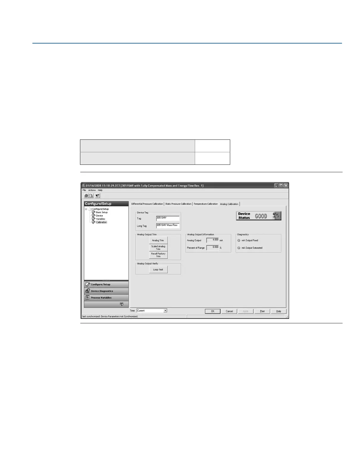
4.3.6 Analog calibration
Figure 4-5. Calibration - Analog Calibration Tab
Analog output trim
The Analog Output Trim commands allow the user to adjust the transmitter’s current output at the 4 and
20 mA points to match the plant standards. This command adjusts the digital to analog signal
conversion, see Figure 4-5.
To perform an analog trim, select the Analog Trim button and follow the on-screen prompts.
Scaled analog output trim
The scaled analog trim command matches the 4 and 20 mA points to a user selectable reference scale
other than 4 and 20 mA (for example, 1 to 5 volts if measuring across a 250 ohm load, or 0 to 100 percent
if measuring from a Distributed Control System [DCS]). To perform a scaled analog trim, connect an
accurate reference meter, select the Scaled Analog Trim button, and follow the on-screen prompts.
Mass and energy flow Fast Keys
1, 2, 5, 2
Direct process variable output Fast Keys
1, 2, 4, 5