70
Reference Manual
00809-0100-4803, Rev GA
Installation
September 2017
Installation
Figure 3-3. Cover Jam Screw
A. Cover jam screw (one per side)
Process flange orientation
Mount the process flanges with sufficient clearance for process connections. For safety reasons, place
the drain/vent valves so the process fluid is directed away from possible human contact when the vents
are used. In addition, consider the need for a testing or calibration input.
3.4.3 Mount the transmitter
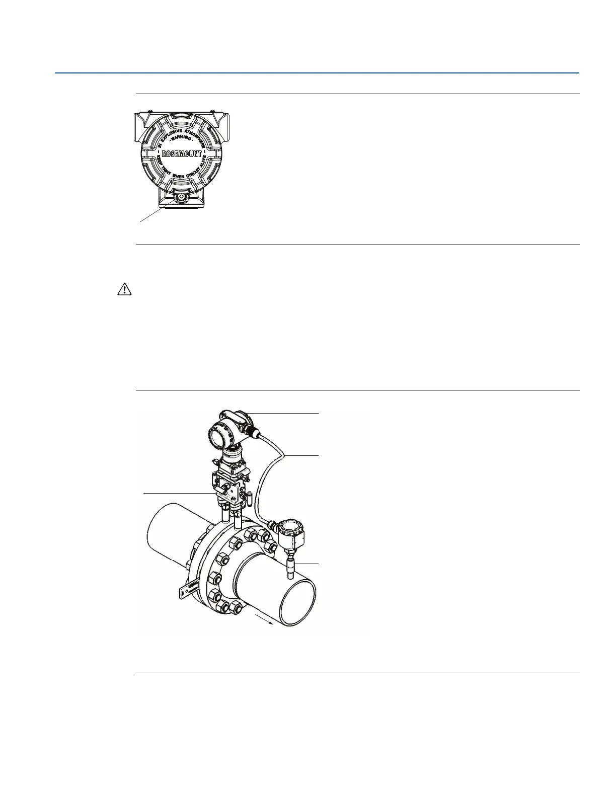
Figure 3-4 illustrates a typical Rosemount 3051SMV installation site measuring dry gas with an orifice
plate.
Figure 3-4. Typical Rosemount 3051SMV Installation Site
A. Rosemount 3051SMV
B. RTD cable
C. Pt 100 RTD sensor
D. Process connections