Specifications and Reference Data
September 2017
Reference Manual
00809-0100-4803, Rev GA
Specifications and Reference Data
132
Temperature limits
Humidity limits
0–100 percent relative humidity
Turn-on time
Performance within specifications less than five seconds for
Rosemount 3051SMV (typical) after power is applied to the
transmitter.
Volumetric displacement
Less than 0.005 in
3
(0,08 cm
3
)
Damping
Analog output response to a step change is user-selectable
from 0 to 60 seconds for one time constant. Each variable
can be individually adjusted. This software damping is in
addition to sensor module response time.
Failure mode alarm
If self-diagnostics detect a gross transmitter failure, the
analog signal will be driven offscale to alert the user.
Rosemount standard (default), NAMUR, and custom alarm
levels are available (see Tab le A -4 ).
High or low alarm signal is software-selectable or
hardware-selectable via the optional switch (option D1).
A.1.3 Physical specifications
Electrical connections
1
/2–14 NPT, G
1
/2, and M20 ⫻ 1.5 (CM20) conduit. HART
interface connections fixed to terminal block.
Process connections
1
/4–18 NPT on 2
1
/8-in. centers
1
/2–14 NPT and RC
1
/2 on 2-in.(50.8 mm),
2
1
/8-in. (54.0 mm), or 2
1
/4-in. (57.2 mm) centers (process
adapters)
Ambient
–40 to 185 °F (–40 to 85 °C)
with LCD display
(1)
: –40 to 175 °F (–40 to 80 °C)
with option code P0: –20 to 185 °F (–29 to 85 °C)
1. CD display may not be readable and LCD display updates will be slower at
temperatures below –4 °F (–20 °C).
Storage
–50 to 185 °F (–46 to 85 °C)
with LCD display: –40 to 185 °F (–40 to 85 °C)
with wireless output: –40 to 185 °F (–40 to 85 °C)
Process temperature limits
At atmospheric pressures and above:
Silicone fill sensor
(2)(3)
2. Process temperatures above 185 °F (85 °C) require derating the ambient
limits by a 1.5:1 ratio. For example, for process temperature of 195 °F
(91 °C), new ambient temperature limit is equal to 170 °F (77 °C). This can be
determined as follows:
(195 °F –185 °F) ⫻ 1.5 = 15 °F,
185 °F–15 °F = 170 °F
3. 212 °F (100 °C) is the upper process temperature limit for DP Range 0.
with coplanar flange –40 to 250 °F (–40 to 121 °C)
(4)
4. 220 °F (104 °C) limit in vacuum service; 130 °F (54 °C) for pressures below 0.5
psia.
with traditional flange –40 to 300 °F (–40 to 149 °C)
(4)(5)
5. –20 °F (–29 °C) is the lower process temperature limit with option code P0.
with level flange –40 to 300 °F (–40 to 149 °C)
(4)
with Rosemount 305
Integral Manifold
–40 to 300 °F (–40 to 149 °C)
(4)(5)
Inert fill sensor
(2)(6)
6. 32 °F (0 °C) is the lower process temperature limit for DP Range 0.
–40 to 185 °F (–40 to 85 °C)
(7)
7. For Rosemount 3051SMV_ _ 1, 2, 140 ° F (60 °C) limit in vacuum service.
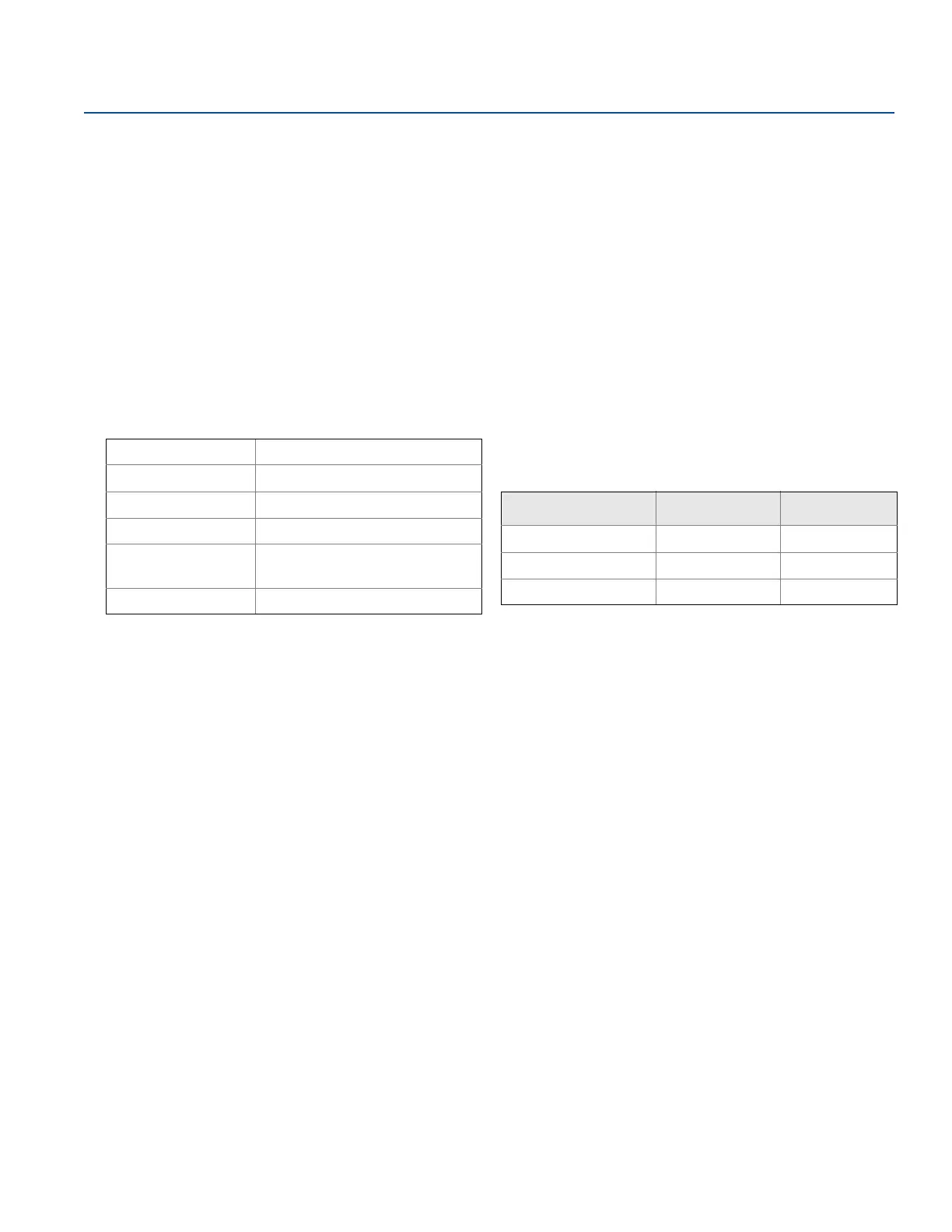
Table A-4. Alarm Configuration
High alarm Low alarm
Default ≥ 21.75 mA ≤ 3.75 mA
NAMUR compliant
(1)
1. Analog output levels are compliant with NAMUR recommendation NE 43,
see option codes C4 or C5.
≥ 22.5 mA ≤ 3.6 mA
Custom levels
(2)
2. Low alarm must be 0.1 mA less than low saturation and high alarm must be
0.1 mA greater than high saturation.
20.2–23.0 mA 3.6–3.8 mA
 Loading...


