73
Reference Manual
00809-0100-4803, Rev GA
Installation
September 2017
Installation
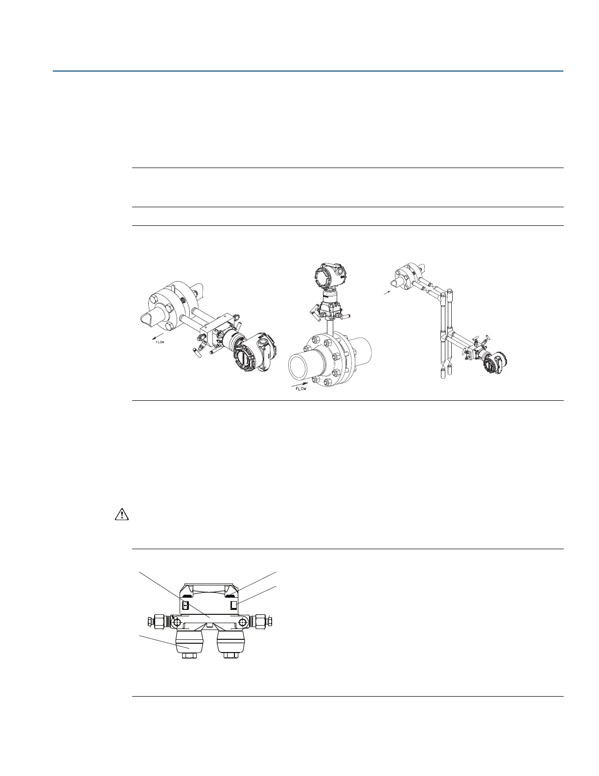
Steam flow measurement
Place taps to the side of the line.
Mount the transmitter below the taps to ensure that impulse piping will remain filled with condensate.
In steam service above 250 °F (121 °C), fill impulse lines with water to prevent steam from contacting
the transmitter directly and to ensure accurate measurement start-up.
Note
For steam or other elevated temperature services, it is important that temperatures at the transmitter
process connection do not exceed the transmitter’s operating limits.
Figure 3-6. Installation Examples
3.4.4 Process connections
The Rosemount 3051SMV flange process connection size is
1
/4–18 NPT. Flange adapters with a
1
/4–18
NPT to
1
/2–14 NPT connection are available with the D2 option. Use a plant-approved lubricant or sealant
when making the process connections. The process connections on the transmitter flange are on 2
1
/8-in.
(54 mm) centers to allow direct mounting to a 3- or 5-valve manifold. Rotate one or both of the flange
adapters to attain connection centers of 2-in. (51 mm), 2
1
/8-in. (54 mm), or 2
1
/4-in. (57 mm).
Install and tighten all four flange bolts before applying pressure to avoid leakage. When properly
installed, the flange bolts will protrude through the top of the SuperModule isolator plate. See
Figure 3-7. Do not attempt to loosen or remove the flange bolts while the transmitter is in service.
Figure 3-7. SuperModule Isolator Plate
A. Bolt
B. SuperModule isolator plate
C. Coplanar flange
D. Flange adapters
Liquid service Gas service Steam service
FLOW