72
Reference Manual
00809-0100-4803, Rev GA
Installation
September 2017
Installation
Torque values for the flange and manifold adapter bolts are as follows:
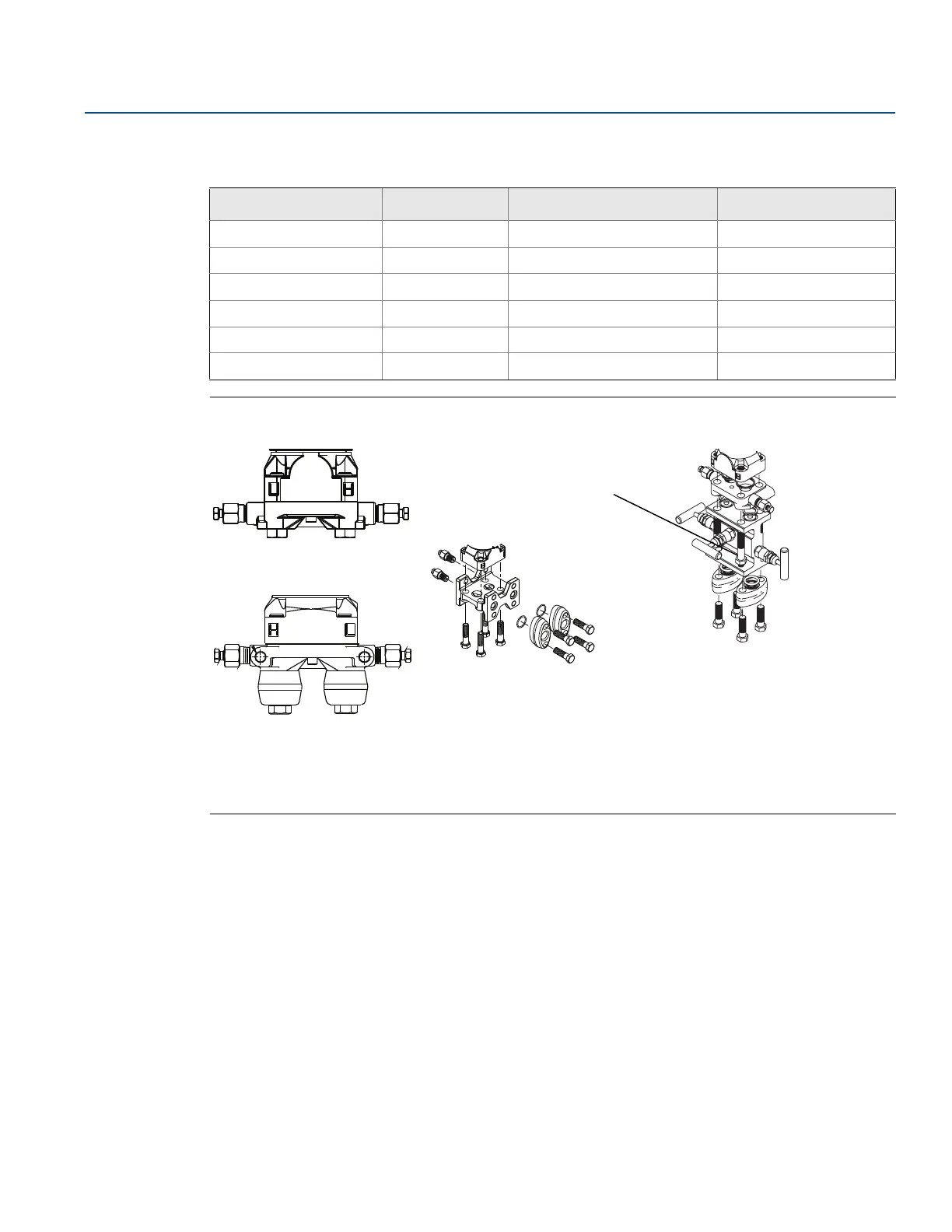
Figure 3-5. Common Transmitter Assemblies
A. Transmitter with coplanar flange
B. Transmitter with coplanar flange and optional flange adapters
C. Transmitter with traditional flange and optional flange adapters
D. Transmitter with coplanar flange and optional manifold and flange adapters
Mounting requirements
Impulse piping configurations depend on specific measurement conditions. Refer to Figure 3-6 on
page 73 for examples of the following mounting configurations:
Liquid flow measurement
Place taps to the side of the line to prevent sediment deposits on the process isolators.
Mount the transmitter beside or below the taps so gases vent into the process line.
Mount drain/vent valve upward to allow gases to vent.
Gas flow measurement
Place taps in the top or side of the line.
Mount the transmitter beside or above the taps so to drain liquid into the process line.
Table 3-2. Bolt Installation Torque Values
Bolt material Option code Initial torque value Final torque value
CS-ASTM-A449 Standard 300 in-lb (34 N-m) 650 in-lb (73 N-m)
316 SST Option L4 150 in-lb (17 N-m) 300 in-lb (34 N-m)
ASTM-A-193-B7M Option L5 300 in-lb (34 N-m) 650 in-lb (73 N-m)
Alloy K-500 Option L6 300 in-lb (34 N-m) 650 in-lb (73 N-m)
ASTM-A-453-660 Option L7 150 in-lb (17 N-m) 300 in-lb (34 N-m)
ASTM-A-193-B8M Option L8 150 in-lb (17 N-m) 300 in-lb (34 N-m)
D
4 × 1.75-in. (44 mm)
4 × 2.25-in. (57 mm)
C
4 × 1.75-in.
(44 mm)
4 × 1.50-in.
(38 mm)