102
Reference Manual
00809-0100-4803, Rev GA
Operation and Maintenance
September 2017
Operation and Maintenance
Install feature board in the Plantweb housing
1. Apply a light coat of low temperature silicon grease to the SuperModule connector O-ring.
2. Insert the SuperModule connector into the top of the SuperModule assembly. Ensure the locking tabs
are fully engaged.
3. Gently slide the feature board into the housing, making sure the pins from the Plantweb housing
properly engage the receptacles on the feature board.
4. Tighten the captive screws.
5. Attach the Plantweb housing cover and tighten so that metal contacts metal to meet
flameproof/explosion-proof requirements.
4.6.3 Terminal block
Electrical connections are located on the terminal block in the compartment labeled “FIELD
TERMINALS.” The terminal block may be replaced or upgraded to add transient protection. Part numbers
can be found in “Service support” on page 117.
Loosen the two captive screws (see Figure 4-12), and pull the entire terminal block out.
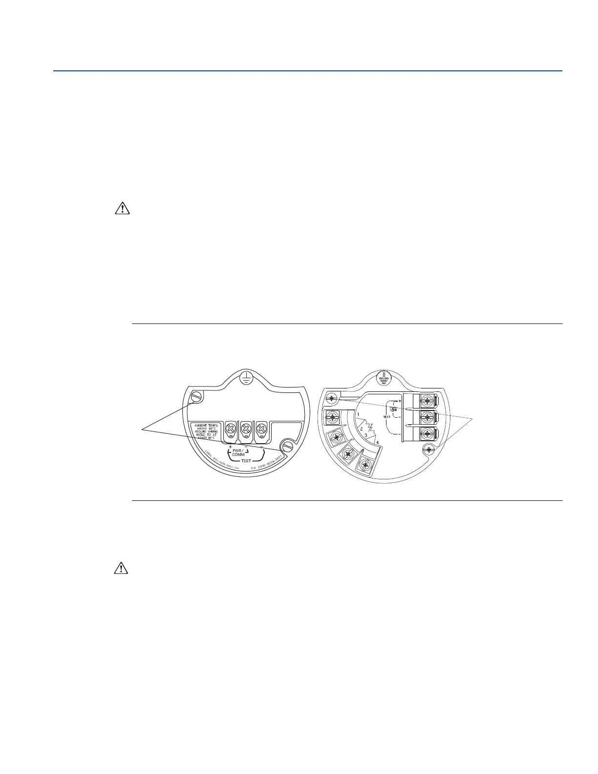
Figure 4-12. Terminal Blocks
A. Captive screws
1. Gently slide the terminal block into the housing, making sure the pins from the Plantweb housing
properly engage the receptacles on the terminal block.
2. Tighten the captive screws on the terminal block.
3. Attach the Plantweb housing cover and tighten so that metal contacts metal to meet
flameproof/explosion-proof requirements.
Without optional
process temperature connections
With optional
process temperature connections