79
Reference Manual
00809-0100-4803, Rev GA
Installation
September 2017
Installation
3.4.6 Conduit electrical connector wiring (option GE or GM)
For Rosemount 3051SMV with conduit electrical connectors GE or GM, refer to the cordset
manufacturer’s installation instructions for wiring details. For FM Intrinsically Safe, non-incendive
hazardous locations, install in accordance with Rosemount drawing 03151-1009 to maintain outdoor
rating (NEMA
®
4X and IP66.) For more information, see “Product Certifications” on page 155.
3.4.7 Grounding
Transmitter case
Always ground the transmitter case in accordance with national and local electrical codes. The most
effective transmitter case grounding method is a direct connection to earth ground with minimal
impedance (< 1Ω). Methods for grounding the transmitter case include:
Internal ground connection
The internal ground connection screw is inside the terminal side of the electronics housing. The screw is
identified by a ground symbol ( ), and is standard on all Rosemount 3051SMV.
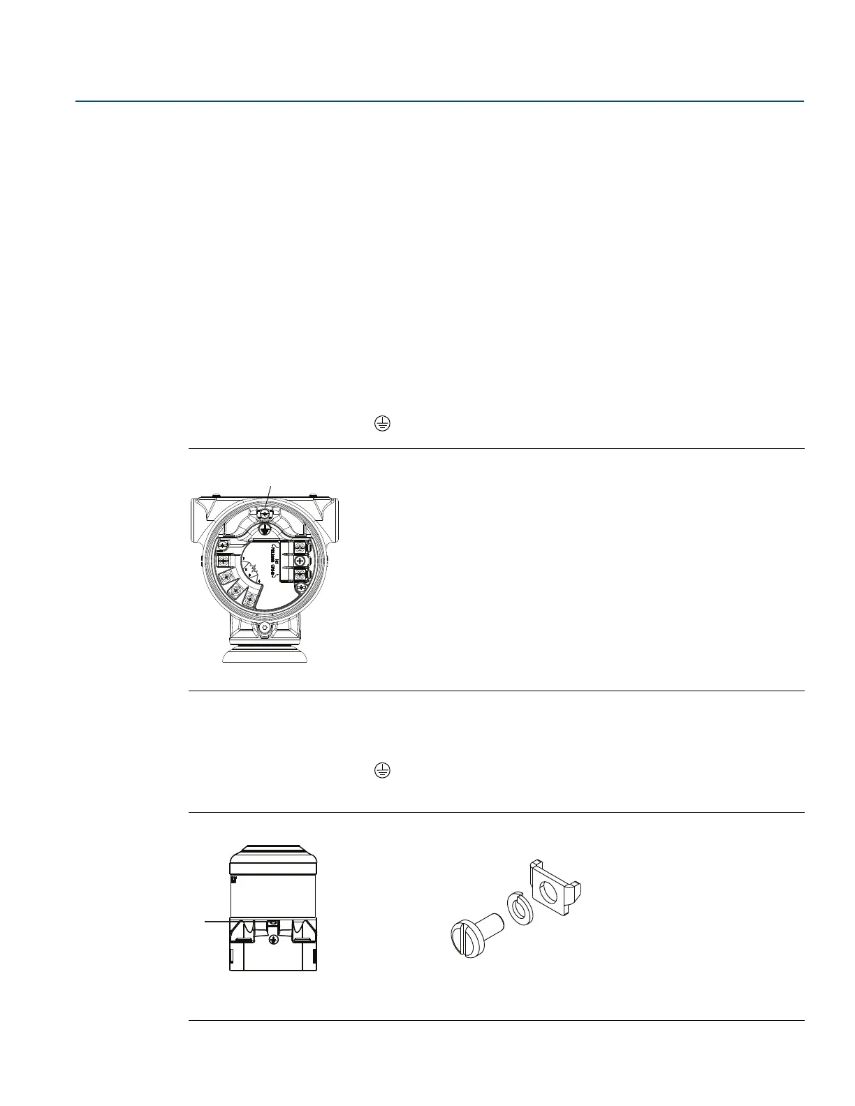
Figure 3-12. Internal Ground Connection
A. Ground lug
External ground connection
The external ground connection is on the outside of the SuperModule housing. The connection is
identified by a ground symbol ( ). An external ground assembly is included with the option codes
shown in Table 3-3 on page 80 or is available as a spare part (03151-9060-0001).
Figure 3-13. External Ground Connection
A. External ground lug
B. External ground assembly (03151-9060-0001)
A
B