75
Reference Manual
00809-0100-4803, Rev GA
Installation
September 2017
Installation
For gas service, slope the impulse piping at least 1 in. per ft. (8 cm per m) downward from the
transmitter toward the process connection.
Avoid high points in liquid lines and low points in gas lines.
Make sure both impulse legs are the same temperature.
Use impulse piping large enough to avoid friction effects and blockage.
Vent all gas from liquid piping legs.
When using a sealing fluid, fill both piping legs to the same level.
When purging, make the purge connection close to the process taps and purge through equal lengths
of the same size pipe. Avoid purging through the transmitter.
Keep corrosive or hot, above 250 °F (121 °C), process material out of direct contact with the
SuperModule process connection and flanges.
Prevent sediment deposits in the impulse piping.
Keep the liquid head balanced on both legs of the impulse piping.
Note
Take necessary steps to prevent process fluid from freezing within the process flange to avoid damage to
the transmitter.
Note
Verify transmitter zero point after installation. To reset zero point, refer to “Sensor trim overview” on
page 90.
3.4.5 Connect wiring and power up
It is recommended to use twisted pair wiring. To ensure proper communication, use 24 to 14 AWG wire,
and do not exceed 5000 ft. (1500 m).
Note
Proper electrical installation is necessary to prevent errors due to improper grounding and electrical
noise. Shielded wiring is recommended for environments with high EMI/RFI levels. Shielded wiring is
required in order to comply with NAMUR requirements.
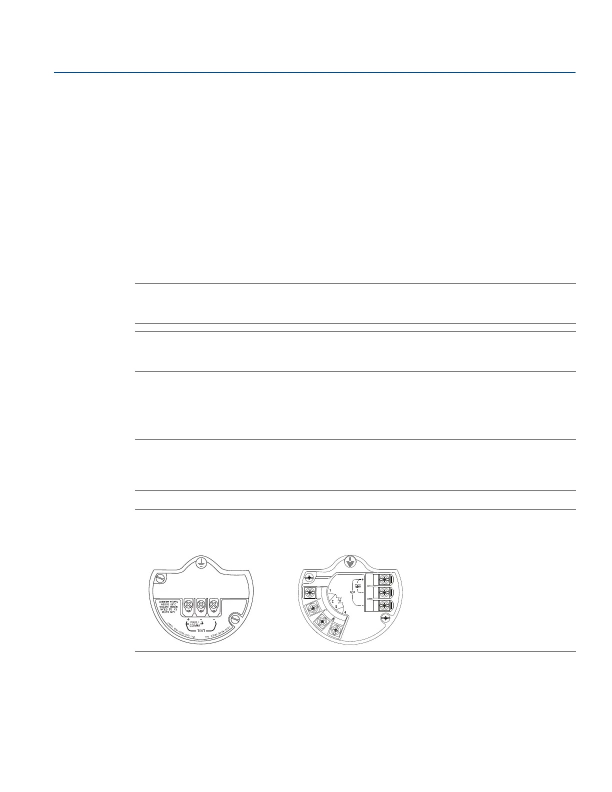
Figure 3-8. Terminal Blocks
To make connections, perform the following procedure:
1. Remove the cover on the field terminals side of the housing.
2. Connect the positive lead to the “PWR/COMM +” terminal, and the negative lead to the “PWR/COMM
–” terminal.
Without optional process
temperature connection
With optional process
temperature connection