74
Reference Manual
00809-0100-4803, Rev GA
Installation
September 2017
Installation
To install adapters to a coplanar flange, perform the following procedure:
1. Remove the flange bolts.
2. Leaving the flange in place, move the adapters into position with the O-rings installed.
3. Attach the adapters and the coplanar flange to the transmitter SuperModule assembly using the
longer of the bolts supplied.
4. Tighten the bolts. Refer to Table 3-2 on page 72 for torque specifications.
Refer to “Service support” on page 117 for the correct part numbers of the flange adapters and O-rings
designed for the Rosemount 3051SMV.
Note
The two styles of Rosemount flange adapters (Rosemount 3051S/3051/2051) each require a unique
O-ring . Use only the O-ring designed for the corresponding flange adaptor.
O-ring
Impulse piping considerations
The piping between the process and the transmitter must accurately transfer the pressure to obtain
accurate measurements. There are many possible sources of error: pressure transfer, leaks, friction loss
(particularly if purging is used), trapped gas in a liquid line, liquid in a gas line, density variations between
the legs, and plugged impulse piping.
The best location for the transmitter in relation to the process pipe depends on the process itself. Use the
following guidelines to determine transmitter location and placement of impulse piping:
Keep impulse piping as short as possible.
For liquid service, slope the impulse piping at least 1 in. per ft. (8 cm per m) upward from the
transmitter toward the process connection.
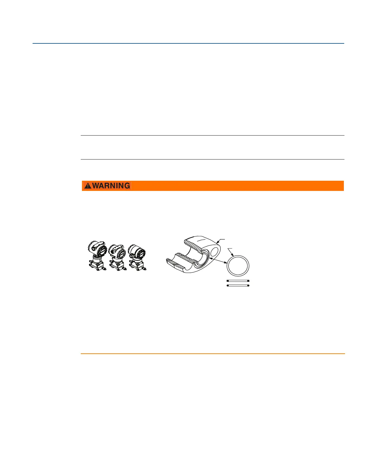
Failure to install proper flange adapter O-rings may cause process leaks, which can result in death or
serious injury. The two flange adapters are distinguished by unique O-ring grooves. Only use the O-ring
designed for its specific flange adapter, as shown below:
A. Flange adapter
B. O-ring
C. PTFE-based profile (square)
D. Elastomer profile (round)
When removing flanges or adapters, visually inspect the PTFE O-rings. Replace them if there are any
signs of damage, such as nicks or cuts. If replacing the O-rings, re-torque the flange bolts after
installation to compensate for seating of the PTFE O-ring. Refer to “Flange and drain vent” on page 103.
A
B
C
Rosemount 3051S/3051/2051
D