78
Reference Manual
00809-0100-4803, Rev GA
Installation
September 2017
Installation
Note
Grounding the transmitter case using the threaded conduit connection may not provide a sufficient
ground. The transient protection terminal block (option code T1) will not provide transient protection
unless the transmitter case is properly grounded. See “Grounding” on page 79 to ground the transmitter
case. Do not run transient protection ground wire with signal wiring; the ground wire may carry
excessive current if a lightning strike occurs.
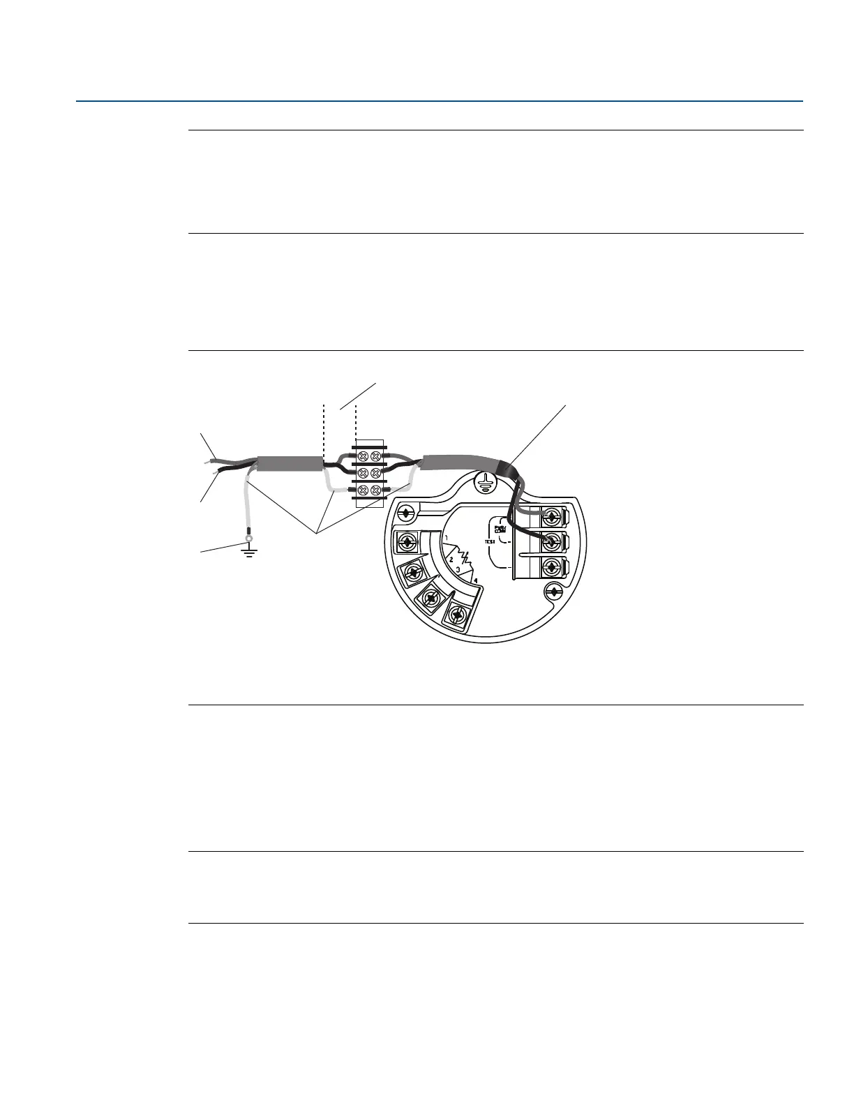
Signal wire grounding
Do not run signal wiring in conduit or open trays with power wiring, or near heavy electrical equipment.
Ground the shield of the signal wiring at any one point on the signal loop. See Figure 3-11. The negative
terminal of the power supply is a recommended grounding point.
Figure 3-11. Signal Wire Grounding
Power supply 4–20 mA transmitters
The DC power supply should provide power with less than two percent ripple. Total resistance load is the
sum of resistance from signal leads and the load resistance of the controller, indicator, and related
pieces. Note that the resistance of intrinsic safety barriers, if used, must be included.
See “Load limitations” on page 131 for transmitter resistance load limits.
Note
A minimum loop resistance of 250 ohms is required to communicate with a Field Communicator. If a
single power supply is used to power more than one Rosemount 3051SMV, the power supply used and
circuitry common to the transmitters should not have more than 20 ohms of impedance at 1200 Hz.
A. Positive
B. Negative
C. Connect shield back to the power supply negative terminal
D. Insulate shield
E. Minimize distance
F. Trim shield and insulate
DP
A
E
B
C
D
F