91
Reference Manual
00809-0100-4803, Rev GA
Operation and Maintenance
September 2017
Operation and Maintenance
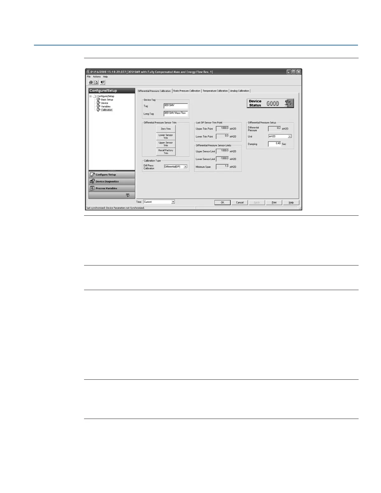
Figure 4-2. Calibration - Differential Pressure Calibration Tab
Zero trim
To perform a DP sensor zero trim, select the Zero Trim button under the Differential Pressure Sensor Trim
heading and follow the on-screen prompts. The transmitter must be within five percent or less of the
maximum span of true zero (zero-based) in order to calibrate with zero trim function.
Note
When performing a DP sensor zero trim, ensure the equalizing valve is open and all wet legs are filled to
the correct levels.
Upper and lower sensor trim
A reference pressure device is required to perform a full sensor trim. Use a reference pressure device that
is at least three times more accurate than the transmitter and allow the pressure input to stabilize for ten
seconds before entering any values. It is possible to degrade the performance of the transmitter if the full
sensor trim is done improperly or with inaccurate calibration equipment.
To perform a DP full trim, perform the following procedure:
1. Select the Lower Sensor Trim button and follow the on-screen prompts.
2. Select the Upper Sensor Trim button and follow the on-screen prompts.
Note
Select process variable calibration input values so that low and high values are equal to or outside the
upper and lower range limits. Do not attempt to obtain reverse output by reversing the high and low
points. The transmitter allows approximately five percent URL deviation from the characterized curve
established at the factory.
Calibration type
The calibration type drop-down menu allows the user to note the type of device last used to calibrate the
sensor (either Differential, Gage, or Absolute). This field does not affect the calibration of the device.