Reference Manual
00809-0100-4809, Rev DA
Appendix A: Specifications and Reference Data
September 2015
90
Specifications and Reference Data
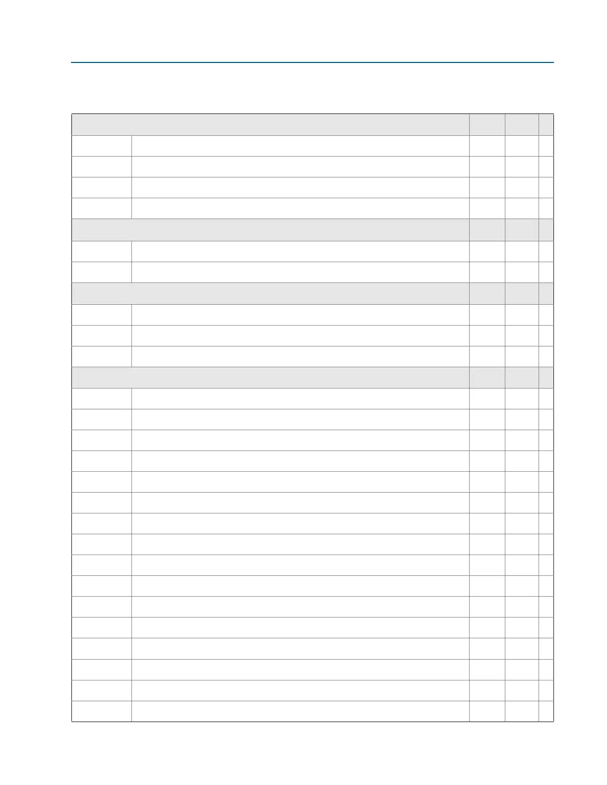
Annubar type D 1-7
F Flanged with opposite side support • • ★
L Flange-Lok • •
G Gear-Drive Flo-Tap • •
M Manual Flo-Tap • •
Sensor material
S 316 Stainless Steel • • ★
H Alloy C-276 • •
Sensor size
1 Sensor size 1 — Line sizes 2-in. (50 mm) to 8-in. (200 mm) • • ★
2 Sensor size 2 — Line sizes 6-in. (150 mm) to 96-in. (2400 mm) • • ★
3 Sensor size 3 — Line sizes greater than 12-in. (300 mm) • • ★
Mounting type
T1 Compression or threaded connection • • ★
A1 150# RF ANSI • • ★
A3 300# RF ANSI • • ★
A6 600# RF ANSI • • ★
D1 DN PN16 flange • • ★
D3 DN PN40 flange • • ★
D6 DN PN100 flange • • ★
A9
(3)
900# RF ANSI • •
AF
(3)
1500# RF ANSI • •
AT
(3)
2500 # RF ANSI • •
R1 150# RTJ flange • •
R3 300# RTJ flange • •
R6 600# RTJ flange • •
R9
(3)
900# RTJ flange • •
RF
(3)
1500# RTJ flange • •
RT
(3)
2500# RTJ flange • •
Table 1. Rosemount 3051SFA Annubar Flowmeter Ordering Information
★ The Standard offering represents the most common options. The starred options (★) should be selected for best delivery.
__The Expanded offering is subject to additional delivery lead time.