Reference Manual
00809-0100-4664, Rev BA
January 2010
5-13
Rosemount 8712
NOTE
Consult factory for installations requiring cathodic protection or situations
where there are high currents or high potential in the process.
The sensor case should always be earth grounded in accordance with
national and local electrical codes. Failure to do so may impair the protection
provided by the equipment. The most effective grounding method is direct
connection from the sensor to earth ground with minimal impedance.
The Internal Ground Connection (Protective Ground Connection) located in
side the junction box is the Internal Ground Connection screw. This screw is
identified by the ground symbol:
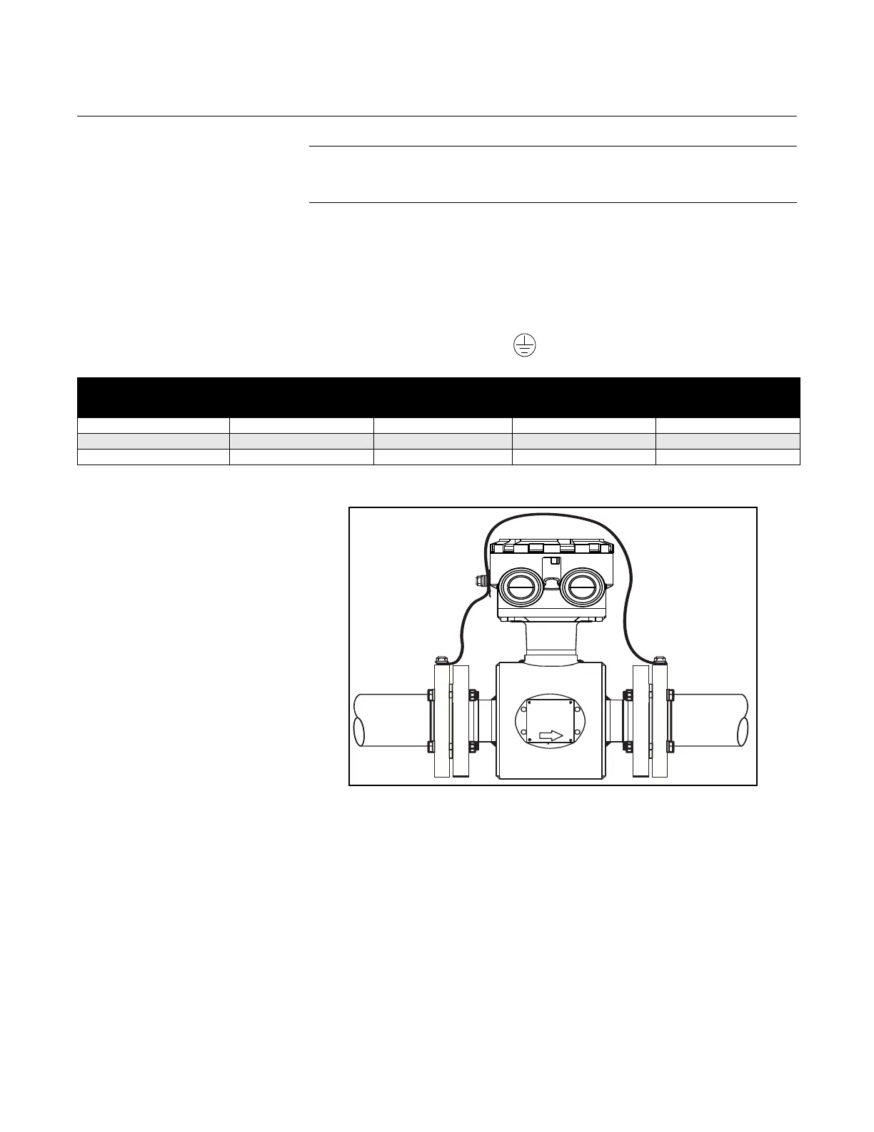
Figure 5-13. No Grounding
Options or Grounding Electrode
in Lined Pipe
Table 5-6. Grounding Installation
Grounding Options
Type of Pipe No Grounding Options Grounding Rings Grounding Electrodes Lining Protectors
Conductive Unlined Pipe See Figure 5-13 Not Required Not Required See Figure 5-14
Conductive Lined Pipe Insufficient Grounding See Figure 5-14 See Figure 5-13 See Figure 5-14
Non-Conductive Pipe Insufficient Grounding See Figure 5-15 See Figure 5-16 See Figure 5-15