Reference Manual
00809-0100-4004, Rev BA
August 2010
5-15
Rosemount 8800D
Removable Support Tube
8. Loosen the four support tube anchor bolts with a
7
/16-in. open end
wrench. (See “”Removable Support Tube Assembly” Figure 5-8)
9. Remove the support tube.
10. Loosen and remove the sensor nut from the sensor cavity with a
1
1
/8-in. (28-mm) open end wrench. (Use a
3
/4-in. (19-mm) open end
wrench for 3- and 4-in. [80 and 100 mm] SST wafers.)
11. Lift the sensor from the sensor cavity. Be very careful to lift the sensor
straight up. Do not rock, twist, or tilt the sensor during removal; this
will damage the engagement diaphragm.
12. Tighten the valve to insure it is closed after the new Vortex sensor is
installed. It is recommended that the nut be torqued to 50 in-lbs (5.7
N-m). Over tightening the valve nut could compromise its ability to
seal.
Cleaning the Sealing Surface
Before installing a sensor in the meter body, clean the sealing surface by
completing the following procedure. The metal o-ring on the sensor is used to
seal the sensor cavity in the event that process fluid should corrode through
the meter body and enter the sensor cavity. Be sure not to scratch or
otherwise damage any part of the sensor, sensor cavity, or sensor nut
threads. Damage to these parts may require replacement of the sensor or
meter body, or may render the flowmeter dangerous.
NOTE
If you are installing a sensor that has been used before, clean the metal o-ring
on the sensor using the procedure below. If you are installing a newly
purchased sensor, cleaning the o-ring is not necessary.
1. Use a suction or compressed air device to remove any loose particles
from the sealing surface and other adjacent areas in the sensor
cavity.
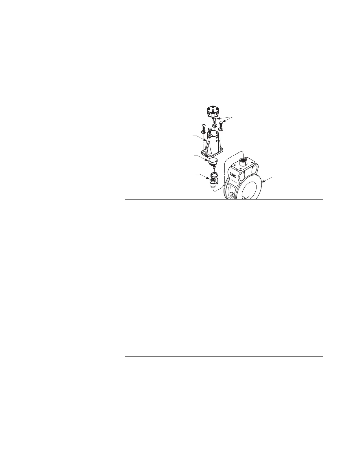
Figure 5-8. Removable Support Tube Assembly
Removable
Support Tube
Sensor Nut
Sensor
Anchor Bolts
Meter Body

 Loading...


