Installation
Page 11 AC-115 Hardware Installation and User's Guide
0
8
5
21
46
3
9
7
#
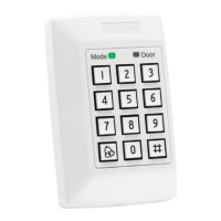
MODE
DOOR
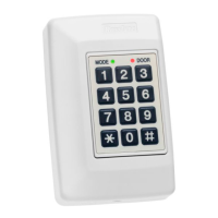
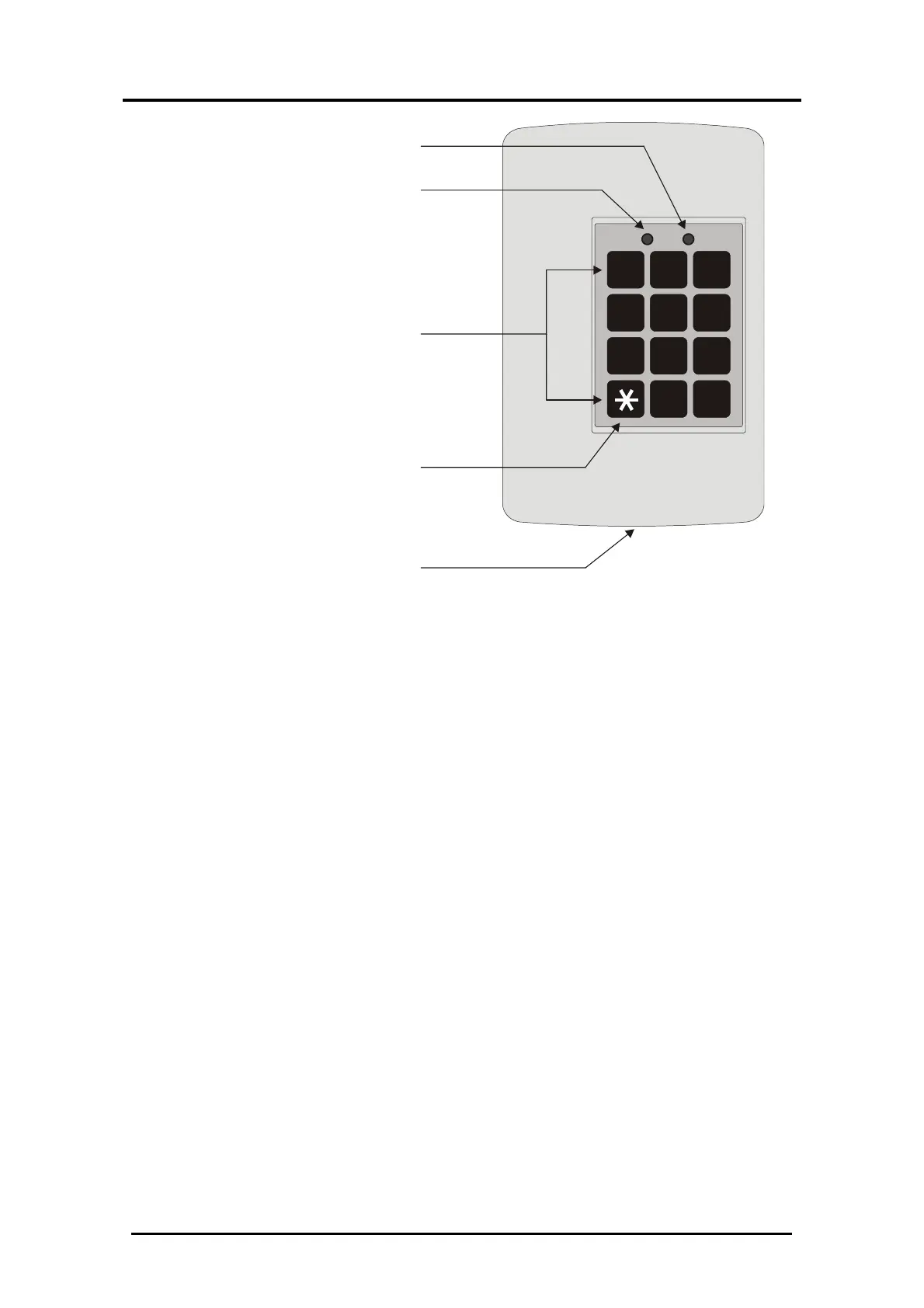
Case Screw
3 x 4 Matrix Keypad
Bell Button
Door LED
Mode LED
Figure 1: Mounting the Controller
6. Wire the controller according to the diagrams on the next
few pages.
7. Return and secure the front case using the security screw
and security tool provided in the Installation Kit.
You have now mechanically installed the controller.
 Loading...