BRP-Rotax
MAINTENANCE MANUAL
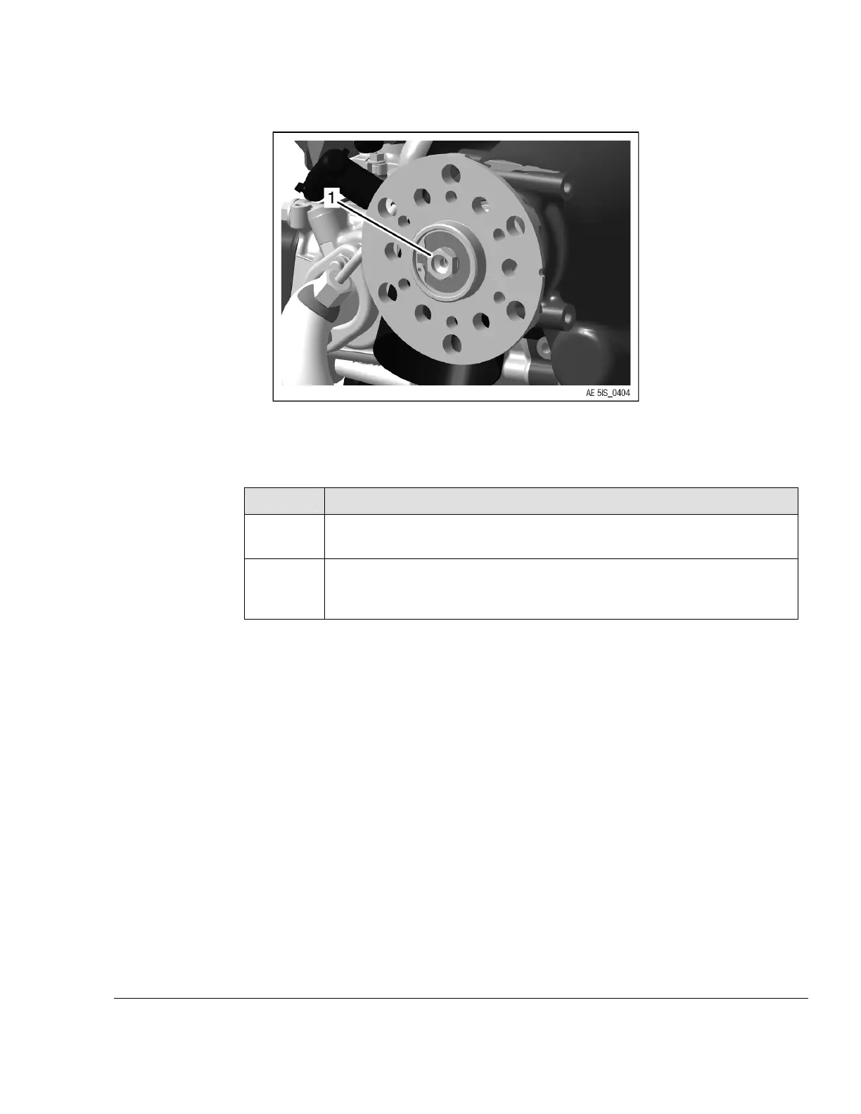
Figure 5.1
1 M12 Hex. screw
Step
Procedure
2
Lock the crankshaft into place. See relevant Maintenance Manual Line for
the respective engine type.
3
Loosen two Hex/Torx-flange screw M8x45 and ten Sk/Torx-flange screws
M6x40 from the gear cover diagonally from each other. The gear cover is
held in place with two dowel pins.
Effectivity: 915 i A Series
Edition 0/Rev. 0
05–50–00
Page 3
December 01 2017

 Loading...


