5.4
Record the Wiring Center zone number that ashes after pushing the pairing button to identify
the wiring center. (Zone 1 = Wiring Center 1, Zone 3 = Wiring Center 3) Refer to the wiring center
installation documentation for identication of wiring centers that exceed the number of zones.
8. Repeat steps 2-6 for each additional AS20WRF/BRF Thermostat.
9. When all AS20WRF/BRF thermostats have been set up, press & hold the ashing button on the
AC10RF Coordinator to complete pairing. The button light will stop ashing and stay solid red.
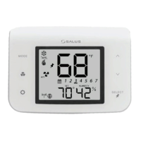
When the thermostat is successfully paired, the screen on the AS20WRF/BRF Thermostat will display
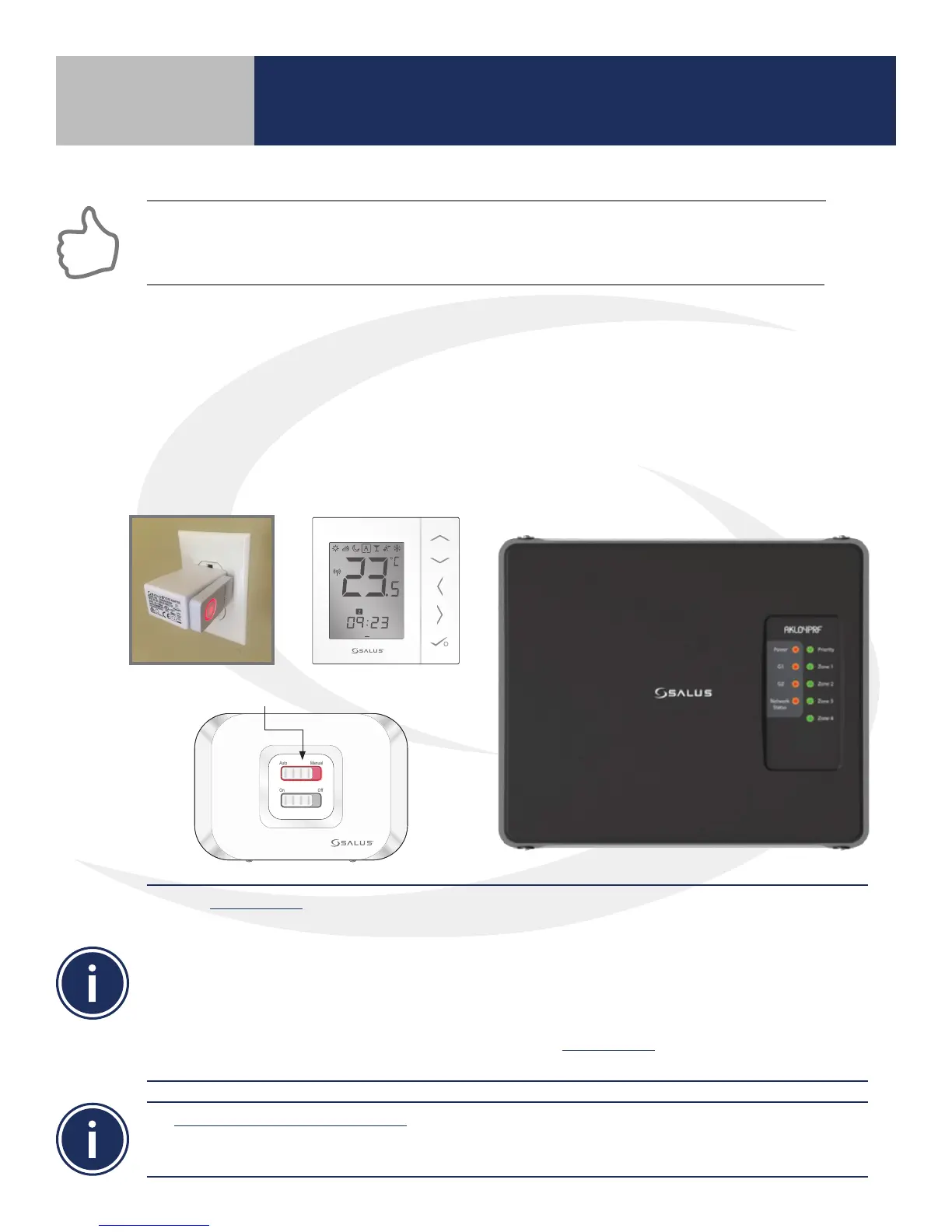
the current temperature, the Network Status Light on the AKL-RF Series Wiring Center will be solid
red and, if applicable, the LED back light on the AX10RF Receiver’s Auto/Manual switch will appear
solid red. The LED button on the AC10RF Coordinator will be solid red.
Use the Identify Mode to check system communication and conguration.
1) Press and release the AC10RF Coordinator button to enter Identify Mode. The light will ash green.
Each item connected will give an indication that it is connected.
a. AKL-RF Wiring Center – G1 & G2 ash red
b. AX10RF Receiver – On/O Switch backlight ashes green
c. . AS20WRF/BRF Thermostat – Displays a 10 minute countdown with the letters “id” below it
until identify times out.
2) Press and release the AC10RF Coordinator button to exit Identify Mode. The light will change to solid
red indicating that the network is active
To delete all devices from the network the following procedure should be used by a qualied contractor.
1) Press and hold the AC10RF Coordinator button for 10 seconds until the light turns AMBER.
2) Once the devices have been deleted, they can be re-installed using the procedures in this manual.
1 2 3 4 5 6 7
PM
Auto Manual
On Off
LED is solid red.
Section 5
Device Pairing & Setup without Internet