Section 6 - Service
80 SCHWARZE HYPERVAC HV-18 revised 11/18
8. Remove the pulley and its bushing from the stub
shaft.
9. Remove the bearing plate from the end of the
auxiliary engine bell housing. Inspect the plate for
irregularities. If none are found, the bearing plate may
be used again.
10. Remove the old stub shaft from the end of the
auxiliary engine.
11. Clean the flywheel and replacement stub shaft using
lacquer thinner.
12. Fasten the replacement stub shaft to the auxiliary
engine using 60 ft. lbs. of torque on each bolt.
13. Use a dial indicator and ensure that the stub shaft is
in-line with the crankshaft. The stub shaft must be no
more than .008” off-center.
If the stub is more than .008” off-center,
it should be replaced.
14. Place the replacement bearing onto the end of the
shaft. Using a piece of pipe placed over the stub
shaft’s end, drive the bearing down the stub shaft until
it rests against its seat.
15. Slip the bearing plate down the stub shaft and onto
the bearing.
16. Bolt the bearing plate too the auxiliary engine.
17. Slide the stub shaft pulley and its taper-lock bushing
onto the end of the stub shaft.
18. Insert the bolts through the taper-lock bushing onto
the end of the stub shaft.
19. Check the alignment of the pulleys, using a string or
straight edge, from the face of one pulley to the face
of the other to determine whether the pulleys are in
line with each other.
20. If the pulleys are misaligned, back the stub shaft
pulley off its bushing, move both in the proper
direction for alignment, them retighten the bushing/
pulley bolts.
21. Inspect the drive belt for wear and replace it with a
new one if needed.
22. Slide the drive belt onto the stub shaft and fan shaft
pulleys.
23. Tighten the belt tension as outlined in the ‘Drive Belt
Tension Adjustment’ section.
24. Replace the belt guard.
Adjusting the Drive Belt Tension
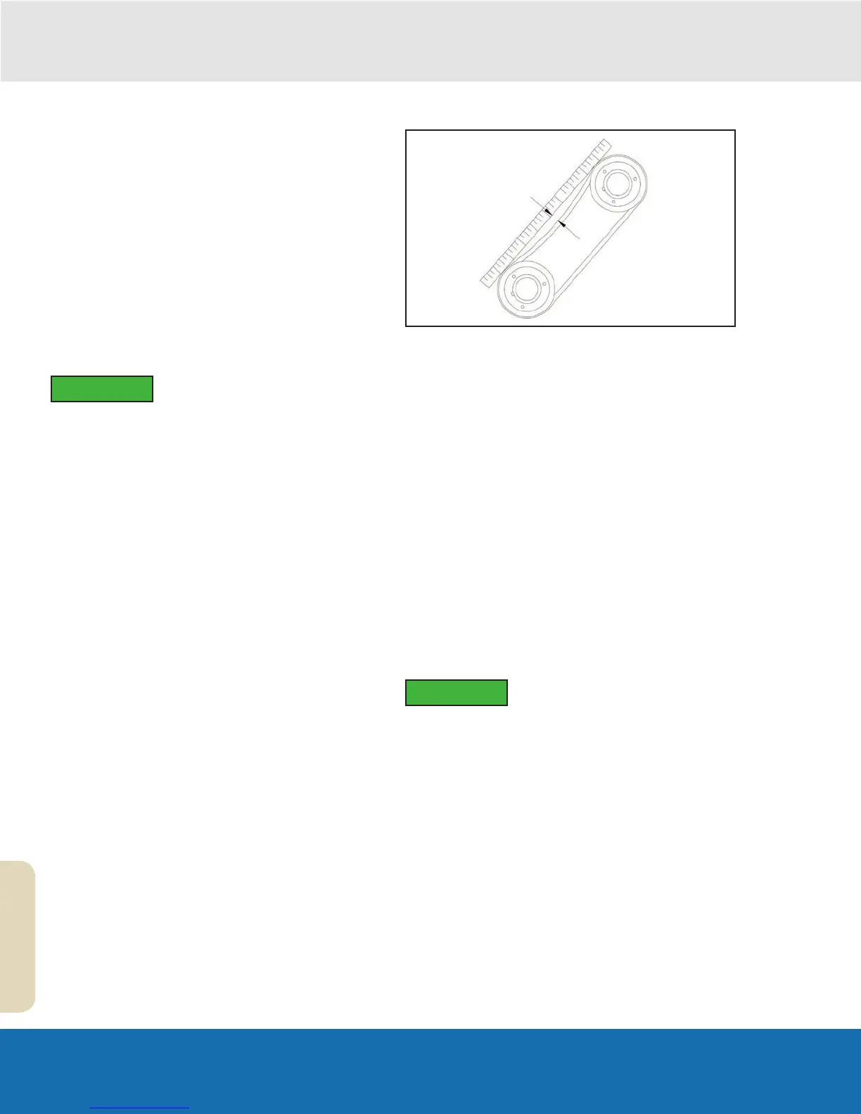
The drive belt is a belt that drives the fan shaft. Check the
belt tension periodically. This is accomplished by pressing
down on the belt halfway between the two pulleys. With
35- 40 lbs. of pressure (the approximate equivalent of
very rm pressure from on it from your thumb), the belt
should deect about 1/2” - 3/8”. An average belt, over the
course of its life, will stretch slightly and the belt will need
adjustment. This will be especially true during the rst 75-
100 hours of operation.
The auxiliary engine, along with its engine skid, can
be moved in the direction of the fan shaft (to loosen or
remove the belt) or away from the fan shaft (to tighten the
belt).
1. Loosen the bolts that connect the two piece belt
guard.
2. Loosen (but do not remove) the bolt which holds each
of the four outer corners of the engine skid to the top
of the power module platform.
3. Locate the threaded rods known as jackscrews.
Before adjusting the jackscrews, mark
the present position of the engine
skid, both at the front and rear, on the
power module platform. This will allow
you to determine how far the engine
skid has been moved and whether the
center line of the auxiliary engine is still
parallel with the fan shaft.
4. Loosen the jackscrews’ jam nuts.
5. By running the adjustment nuts in or out, the engine
skid may be moved toward or away from the shaft.
Alternate adjusting the jackscrew nuts front to rear
so that movement of the engine skid is even and the
engine skid does not become misaligned. If you turn
the front jackscrew three revolutions, then turn the
rear jackscrew three revolutions.
IMPORTANT
IMPORTANT