Section 6 - Service
HV-18 revised 11/18 SCHWARZE HYPERVAC 87
Checking the Solenoid Control Valve
In the hydraulic system, uid ow direction is used to
control the various hydraulic functions. The directional
valve determines the ow direction. If the directional valve
is faulty and unable to reverse the hydraulic uid ow,
the directional valve’s hydraulic function will not operate
properly.
Override Check
1. Locate the directional valve attached to the manifold
block of the power module.
2. Locate the solenoid and two plugs that are attached
with wires at either end of the directional valve. Each
plug contains a small light that illuminates whenever
that solenoid is electrically activated.
3. With the auxiliary engine running, toggle the in-
cab console control panel switch that controls the
hydraulic function for that particular directional valve.
4. One of the two lights should illuminate, indicating
power is being supplied to that side of the directional
valve. If neither light operates, the directional valve is
not receiving power and the problem is electrical.
5. If the directional valve lights operate when the incab
console control panel switch is toggled, the problem
may be within the directional valve.
6. On either end of the directional valve is a small
hole, about 1/8” in diameter. With the auxiliary
engine running, insert a small nail or small Phillips
screwdriver to insert into the holes (one at a time) at
either end of the directional valve to manually override
the directional valve. There is an initial easy push of
the plunger, then a greater amount of pressure must
be used to overcome the spring. If this procedure
corrects the hydraulic function problem, then the
directional valve is faulty and should be repaired or
replaced.
For dust suppression during sweeping operations, water
ows from the water reservoirs and through the ‘Y’
strainer and the hydraulically-driven water pump. Then, it
goes through the water manifold and hoses to the spray
nozzles.
Water being drawn from the water reservoir to the water
pump passes through the Y strainer screen, trapping
and preventing debris from reaching the rest of the dust
suppression system.
We recommend the maintenance listed in the following
table:
Service Frequency
Clean the ‘Y’ Strainer Daily
Inspect and clean the nozzles Daily
Winterize the system When Needed
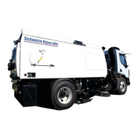
Refilling the Water Tank
1.
Remove water fill inlet cover
2.
Attach a hydrant hose to water tank
3. Water will flow into the fill point on the top of the front
tank.
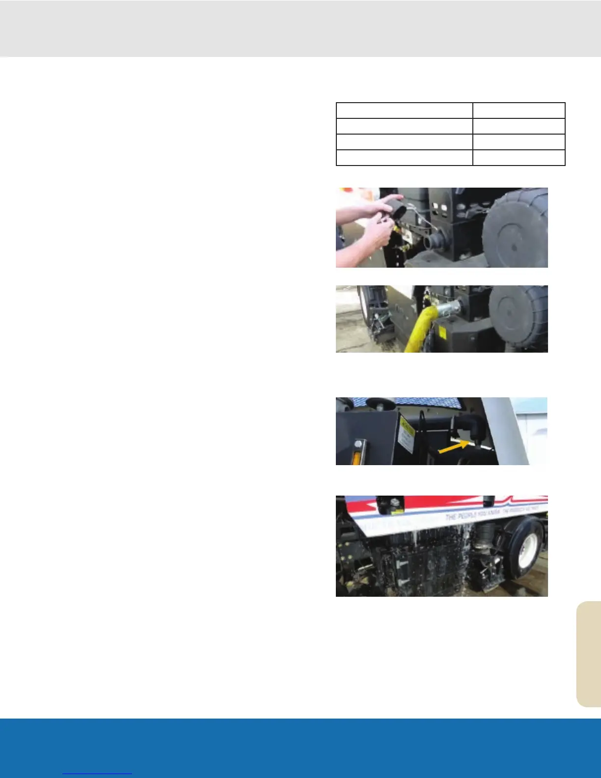
4.
To fill both the front tank and rear tank, make sure the
rear fill valve is open.
5.
When full, water will spill out from the top fill port of
the front tank.
Note: The combined tanks capacity is around 250 gallons.