9.13
Date Code 20020903 SEL-587Z Instruction Manual
Event Reports and SER
Event Reports
Example
Event Report
The example event report shown in Figure 9.2 on page 9.15 is from a report
generated with the EVE command.
In Figure 9.2 on page 9.15, the arrow (>) in the column following the IC
current column identifies the “trigger” row. This is the row that corresponds to
the Date and Time values at the top of the event report.
The asterisk (*) in the column following the IC current column identifies the
row with the maximum phase current. The maximum phase current is
calculated from the row identified with the asterisk and the row one-quarter
cycle previous. These currents are listed at the end of the example event
report. If the “trigger” row (>) and the maximum phase current row (*) are the
same row, the * symbol takes precedence and is displayed. Because the relay
samples at 1/8-cycles, the 1/4-cycle report contains only half of the processed
information. To ensure the asterisk (*) and arrow (>) appear in the event
report, use the 1/8-cycle report.
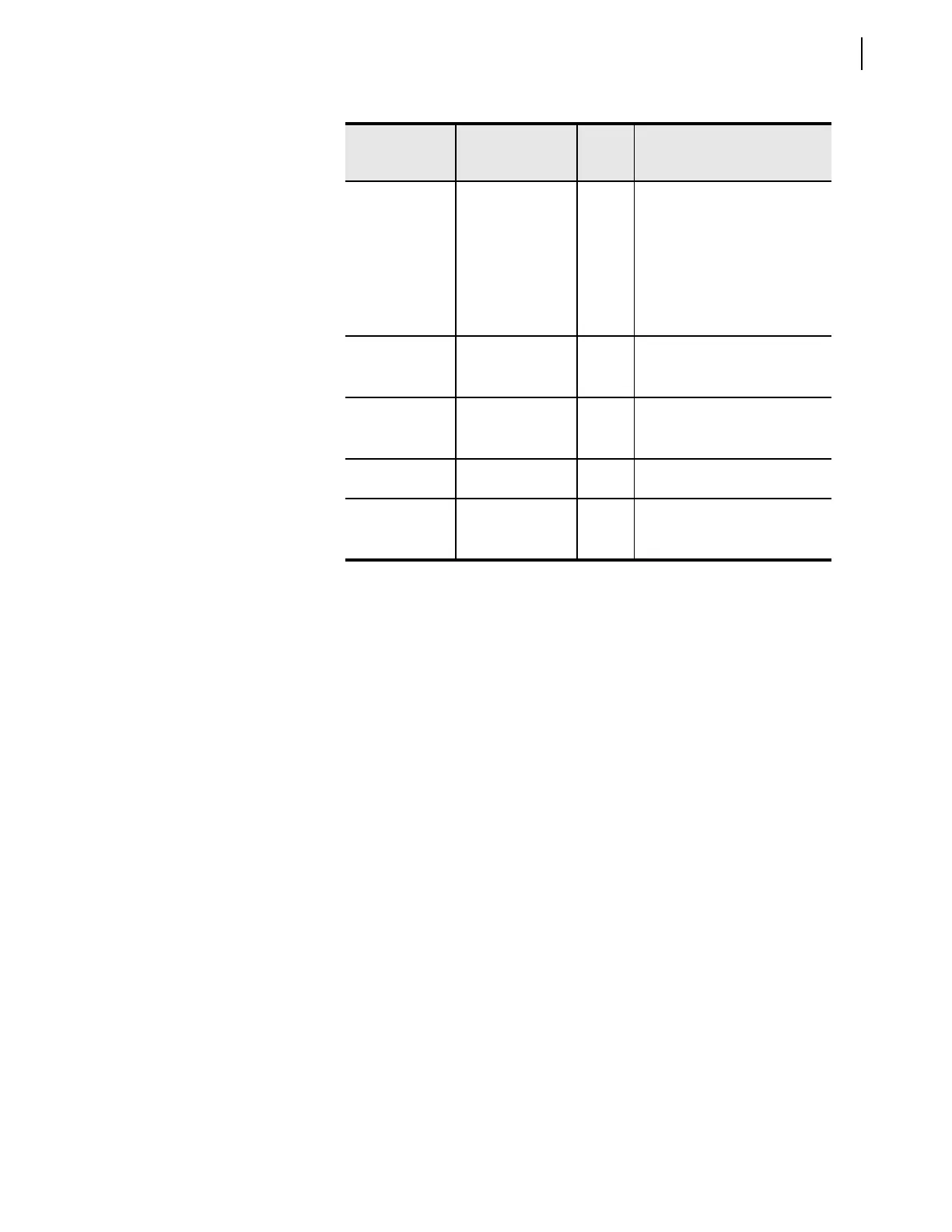
SV 14T SV14, SV14T p
T
d
SELOGIC control
equation variable SV14
asserted; timer not timed out
SEL
OGIC control
equation variable SV14
asserted and timer SV14T asserted
SEL
OGIC control
equation variable SV14
deasserted; timer SV14T asserted
Out 1&2
a
OUT1, OUT2 1
2
b
Output contact OUT1 asserted
Output contact OUT2 asserted
Both OUT1 and OUT2 asserted
Out 3&4
a
OUT3, OUT4 3
4
b
Output contact OUT3 asserted
Output contact OUT4 asserted
Both OUT3 and OUT4 asserted
Out ALM ALARM A Relay failed or PULSE A
command issued
In1&2 IN1, IN2 1
2
b
Optoisolated input IN1 asserted
Optoisolated input IN2 asserted
Both IN1 and IN2 asserted
a
Output contacts can be A or B type contacts (see Output Contact Jumpers on page 2.8 in
Section 2: Installation).
Table 9.4 Digital Element Columns (Sheet 7 of 7)
Column Heading
Corresponding
Elements
(Relay Word Bits)
Symbol Definition


 To Next Page