4.9
Date Code 20020903 SEL-587Z Instruction Manual
Control Logic
Remote Control Switches
Remote Control Switches
Remote control switches are operated via the serial communications port only
(see CON (Control) on page 7.7 in Section 7: ASCII Command Reference).
These switches differ from local control switches in that remote control
switches are operated via serial communications only, and local control
switches are operated via the front-panel keyboard/display only.
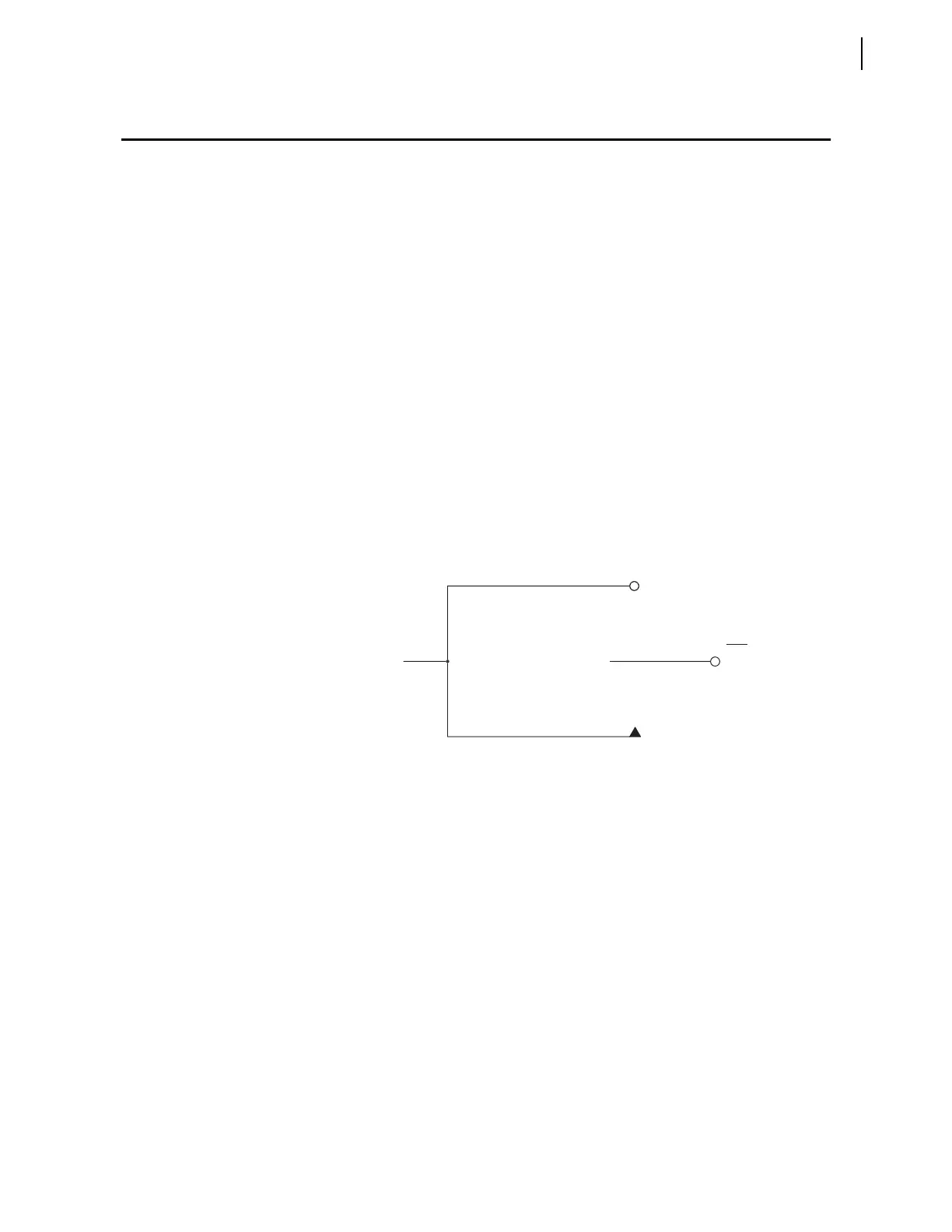
The output of the remote control switch in Figure 4.4 is a Relay Word bit
(remote bit RBn, n = 1 through 8). These remote bits are used in SEL
OGIC
control equations.
Any remote control switch can be put in one of the following three positions:
ON–(logical 1)
OFF–(logical 0)
MOMENTARY–(logical 1 for one processing interval)
With SEL
OGIC control equations, the remote bits can be used in applications
similar to those for which local bits are used (see Local Control Switches
(NLBn, SLBn, CLBn, PLBn) on page 4.5).
Figure 4.4 Remote Control Switches Drive Remote Bits RB1 Through RB8.
Remote Bit States
Not Retained
Power Loss
The states of the remote bits (Relay Word bits RB1 through RB8) are not
retained if power to the relay is lost and then restored. The remote control
switches come back in the OFF position (corresponding remote bit is
deasserted to logical 0) when power is restored to the relay.
ON
ositio
maintaine
lo
ical
osition
OFF
ositio
maintaine
o
ica
osition
MOMENTARY
ositio
(lo
ical 1 for on
rocessin
interval
Lo
ical
RBn
(n=1 through 8)
Relay
Word
Bit