3.5
Date Code 20020903 SEL-587Z Instruction Manual
Relay Elements
High-Impedance Protection
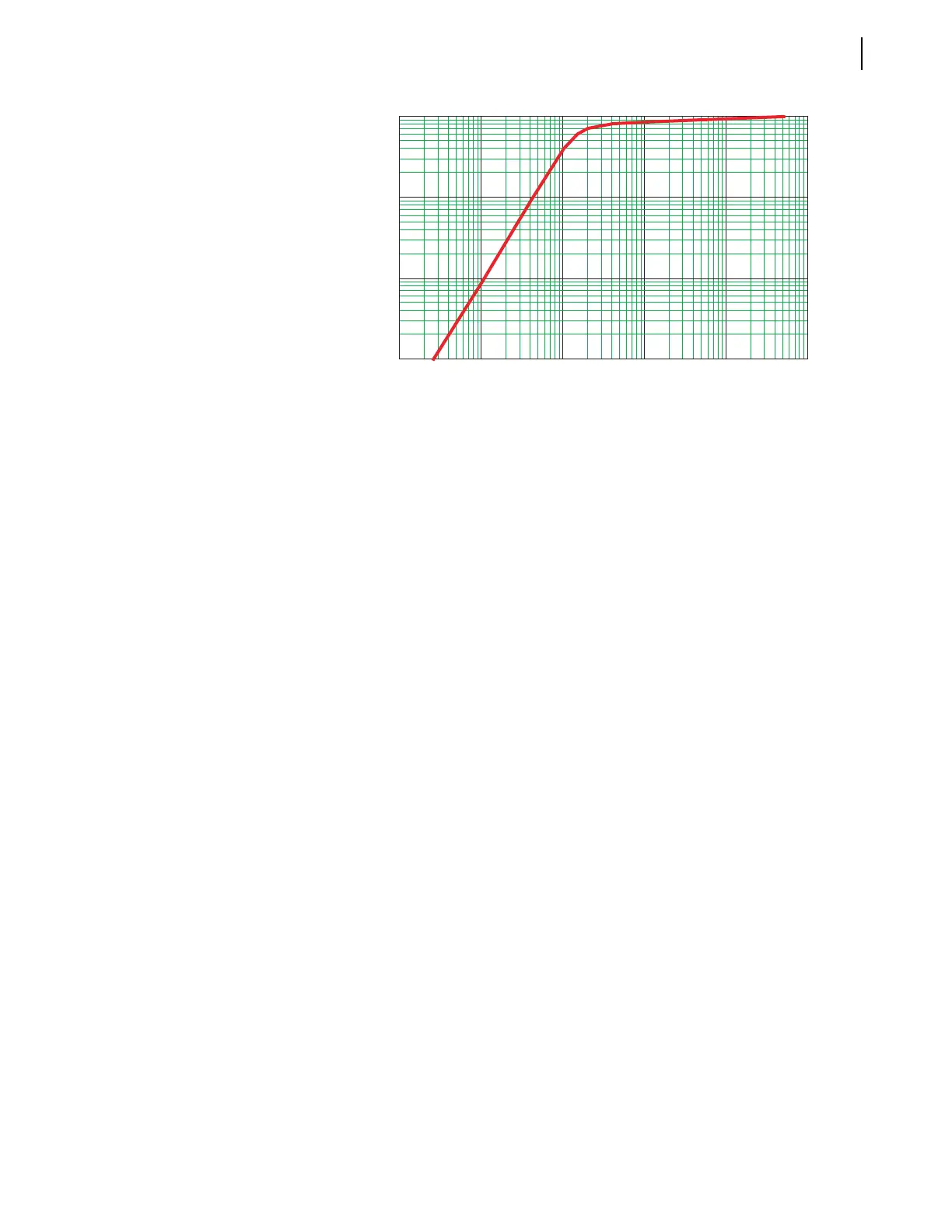
Figure 3.6 CT Characteristic.
This is a very pessimistic value, because the current transformer completely
saturates only under extreme conditions. Comparing the calculated value with
the CT knee-point voltage, Figure 3.6 shows that 178 V is well below the
knee-point voltage of 432 V.
Set the voltage elements of the high-impedance relay for the maximum
possible voltage developed across the elements for an external fault as
follows:
Equation 3.3
where
V
s
= voltage setting
K = a safety factor, representing the necessary security
level and CT performance
For this example, choose K as 150 percent. Follow your company practices for
setting this safety factor in your particular application.
Equation 3.4
Set the high-impedance elements 87A1P = 87B1P = 87C1P = 267 V.
Minimum
Internal Fault
Operating Current
Use the following equation to calculate the minimum primary current required
to operate the relay for an internal fault:
Equation 3.5
0.01 0.10 1.00 10.00 100.00
10
100
1000
Secondary RMS Exciting Volts
Secondary RMS Exciting Amperes
V
s
KV
r
• =
V
s
1.5 V
r
• =
1.5 178• =
267 V=
I
min
nI
e
I
r
I
m
++• ()N• =