3.9
Date Code 20020903 SEL-587Z Instruction Manual
Relay Elements
High-Impedance Protection
Use the high-impedance elements, 87A1, 87B1, and 87C1, for instantaneous
high-impedance bus protection. Set the voltage elements according to the V
r
calculation (see Equation 3.2 on page 3.4). Use the second set of elements,
87A2, 87B2, and 87C2, to detect CT open-circuit conditions.
Performance
Detection
The application circuit of Figure 3.10 provides high-impedance differential
protection and continuously checks protection scheme operation. This
application uses an external breaker failure lock-out (86) relay.
Breaker Failure/Bus Fault Cleared Detection
With reference to Figure 3.10, connect the 50/51 elements and 86 contacts as
shown. Following a bus fault, the 86 contacts short out the high-impedance
elements, and the entire fault current flows through the 50/51 elements. Delay
operation of the 50/51 elements for a suitable period to give all circuit
breakers time to open. An element still picked up after the time delay indicates
one or more circuit breakers have failed to open. Use the 50/51 elements to
send a direct trip command to all adjacent substations to clear the fault, or
assign them to supervise SCADA attempts to reenergize the bus.
MOV Degradation Detection and Back-Up Protection
Metal oxide varistors are in parallel with the resistors to clamp the voltage to
less than 2 kV during bus faults. With degradation, the MOV may conduct
larger current at lower applied voltages. At various degrees of MOV failure
(short circuit), more current flows through the MOV, shunting current away
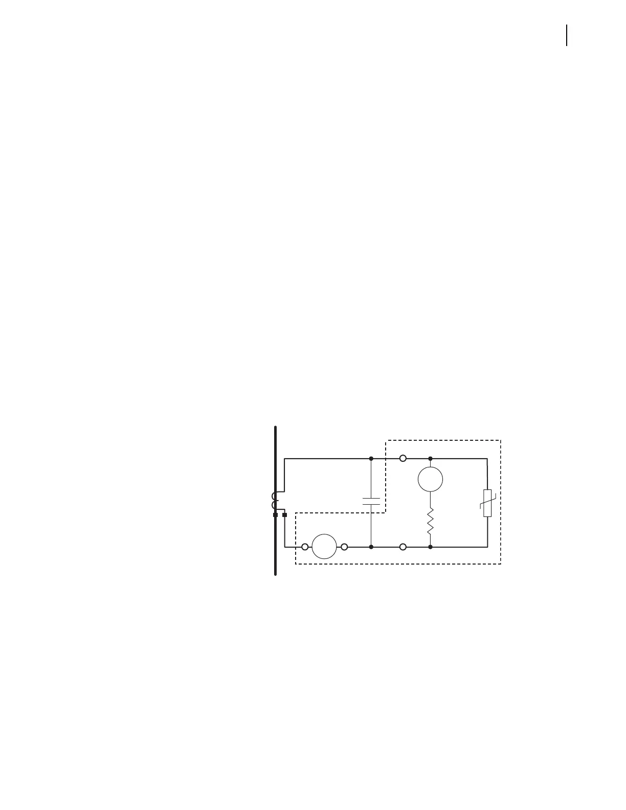
from the high-impedance elements. Figure 3.10 shows the application of the
50/51 overcurrent elements to detect this condition.
Figure 3.10 Overcurrent Elements in Differential Circuit (one phase shown).
In Figure 3.10:
R = 2000
Ω stabilizing resistor
86 = contact from the lock-out relay
50/51 = low-impedance overcurrent element
During normal balanced system conditions, the voltage measured across the
high-impedance element is very low (theoretically zero), and very little
current flows through the MOV. Therefore, the 50/51 elements are only
effective to detect MOV failure during external faults (with one of the CTs
saturating) or bus faults. However, the 50/51 elements provide back-up bus
protection should the MOV fail during a heavy bus fault.
Stabilizing
Resistor
R
86
87Z
50/51
MOV
107 108 102
101
SEL-587Z