10.10
SEL-587Z Instruction Manual Date Code 20020903
Testing and Troubleshooting
Acceptance Testing
Instantaneous
Overcurrent
Elements
Step 1. Purpose: Determine the expected instantaneous overcurrent
element pickup value.
Method: Execute the SHO command via the relay front panel
or serial port and verify the setting (i.e., SHO 50A1P<Enter>).
Step 2. Purpose: Display the appropriate Relay Word bit on the front-
panel LEDs.
Method: Execute the TARGET command (i.e., TAR 3
<Enter>). The SEL-587Z now displays the state of several
overcurrent elements on the front-panel LED and LCD display.
More overcurrent elements are on the next row; to view their
status, type in TAR 4<Enter>.
Step 3. Purpose: Connect and apply a single current test source until
the appropriate LED illuminates.
Method: Connect a single current test source (i.e., source 1 to
current input IA) as shown in Figure 10.5 on page 10.9. Turn
on the current test source for the phase under test, and slowly
increase the magnitude of current applied until the appropriate
element asserts (i.e., 50A1), causing the LED to illuminate (i.e.,
top row, right hand side; see Table 10.2. Note the magnitude of
the current applied. It should equal the 50A1P setting ±5% of
the setting and ±0.1 A secondary.
Step 4. Purpose: Repeat test for each instantaneous overcurrent
element.
Method: Repeat steps 1 through 3 for each instantaneous
overcurrent element listed in Table 10.2. Remember to view the
element with the TAR command (see Table 10.2). The
computer terminal will display the LED labels from left to right
when the TAR command is issued.
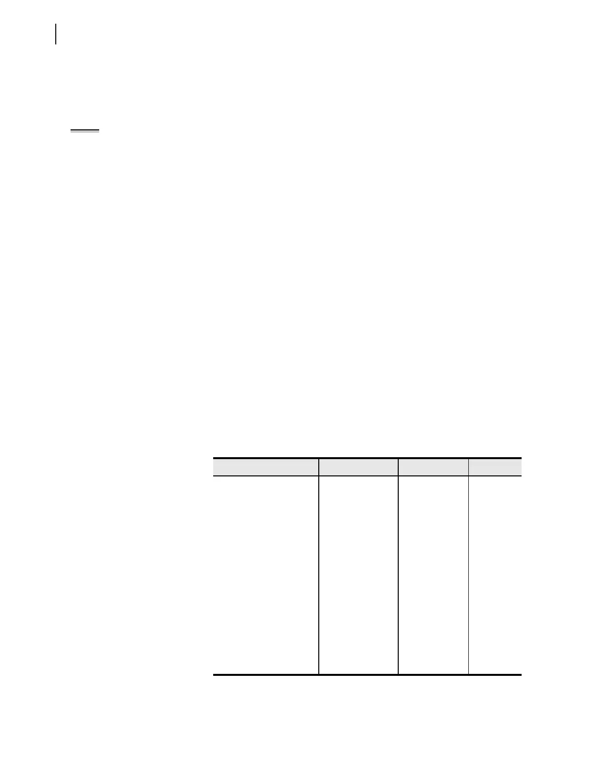
Table 10.2 Instantaneous Overcurrent Elements and
Corresponding Settings/Relay Word Bits/TAR Commands
Element Pickup Setting Relay Word Bit TAR
A-phase Level 1 50A1P 50A1 3
A-phase Level 2 50A2P 50A2 3
B-phase Level 1 50B1P 50B1 4
B-phase Level 2 50B2P 50B2 4
C-phase Level 1 50C1P 50C1 4
C-phase Level 2 50C2P 50C2 4
Maximum Phase Level 1 50P1P 50P1 3
Maximum Phase Level 2 50P2P 50P2 3
Maximum Phase Level 3 50P3P 50P3 3
Residual Ground Level 1 50G1P 50G1 4
Residual Ground Level 2 50G2P 50G2 4
Negative-Sequence Level 1 50Q1P 50Q1 4
Negative-Sequence Level 2 50Q2P 50Q2 4
NOTE: This example tests the 50A1
phase overcurrent element. Use the
same procedure to test all
instantaneous overcurrent elements
for each phase.

 Loading...


