D.16
SEL-587Z Instruction Manual Date Code 20020903
Modbus RTU Communications Protocol
Modbus Map
Modbus Map
All registers are 16 bits with bit locations ranging from 0 to 15.
Relay Word bits, targets, and contact status are mapped in bit positions 8
through 15 in the Register. The 0 bit position of this Register is set equal to 1
if any of the 1–15 positions are set to 1.
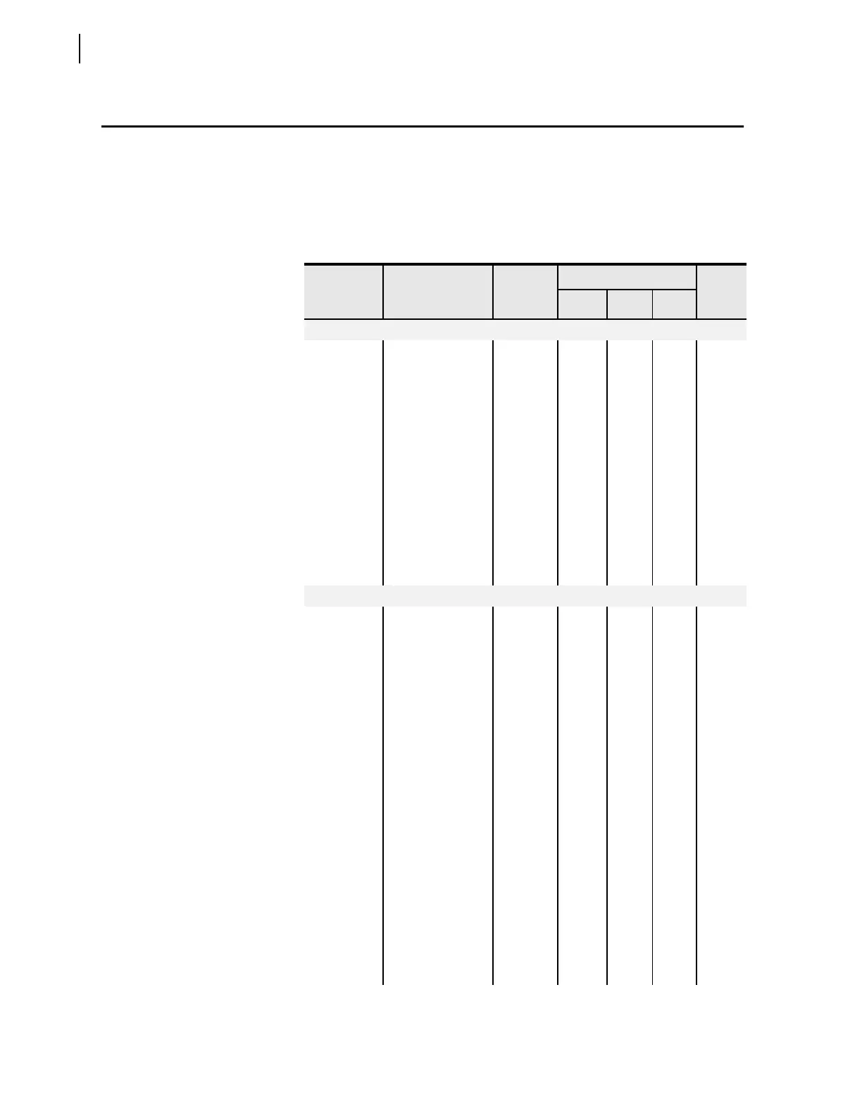
Table D.18 Modbus Map (Sheet 1 of 15)
Address
(Hex)
Field Units
Range
Scale
Factor
Low High
Step
Relay ID
0000–0016 FID
a
ASCII
String
––––
0017–0019
Revision
a
ASCII
String
––––
001A–0022
Relay ID
a
ASCII
String
––––
0023–002B
Terminal ID
a
ASCII
String
––––
002C Reserved
(see NOTE 1)
002D
Device Tag #
b
15047 ––––
002E
Feature Set ID
b
0 ––––
002F Reserved
Relay Status
0030 Channel 87A
offset value
c
mV –5000 5000 1 1
0031
Channel 87A
status message
b
0 = OK
1 = Warn
2 = Fail
–––––
0032
Channel 87B
offset value
c
mV –5000 5000 1 1
0033
Channel 87B
status message
b
0 = OK
1 = Warn
2 = Fail
–––––
0034 Channel 87C
offset value
c
mV –5000 5000 1 1
0035
Channel 87C
status message
b
0 = OK
1 = Warn
2 = Fail
–––––
0036
Channel IA
offset value
c
mV –5000 5000 1 1