2.8
SEL-587Z Instruction Manual Date Code 20020903
Installation
Circuit Board Jumpers and Battery
Circuit Board Jumpers and Battery
Control
Voltage Jumpers
The SEL-587Z has field-changeable jumpers that select the control voltage for
two digital inputs. Refer to Section 1: Introduction and Specifications for
details on operating voltage and current levels.
The jumpers are factory configured to the control voltage specified at time of
ordering. The jumpers may be changed as outlined below.
To change the control input voltage range using internal jumpers, take the
following steps:
Step 1. De-energize the relay.
Step 2. Remove the six front-panel screws and the relay front panel.
CAUTION: Equipment
components are sensitive to
electrostatic discharge (ESD).
Undetectable permanent damage
can result if you do not use proper
ESD procedures. Properly ground
yourself, your work surface, and this
equipment before removing any
cover from this equipment. If your
facility is not equipped to work with
these components, contact SEL
about returning this device and
related SEL equipment for service.
!
Step 3. Disconnect the analog signal ribbon cable and the power supply
cable from the underside of the relay main board.
Step 4. Grasp the black knob on the front of the draw-out assembly and
pull the assembly from the relay chassis.
Step 5. Locate the control voltage jumpers near the rear edge of the
relay main board.
The jumpers are numbered JMP6 through JMP11. Refer to
Figure 2.6 on page 2.9.
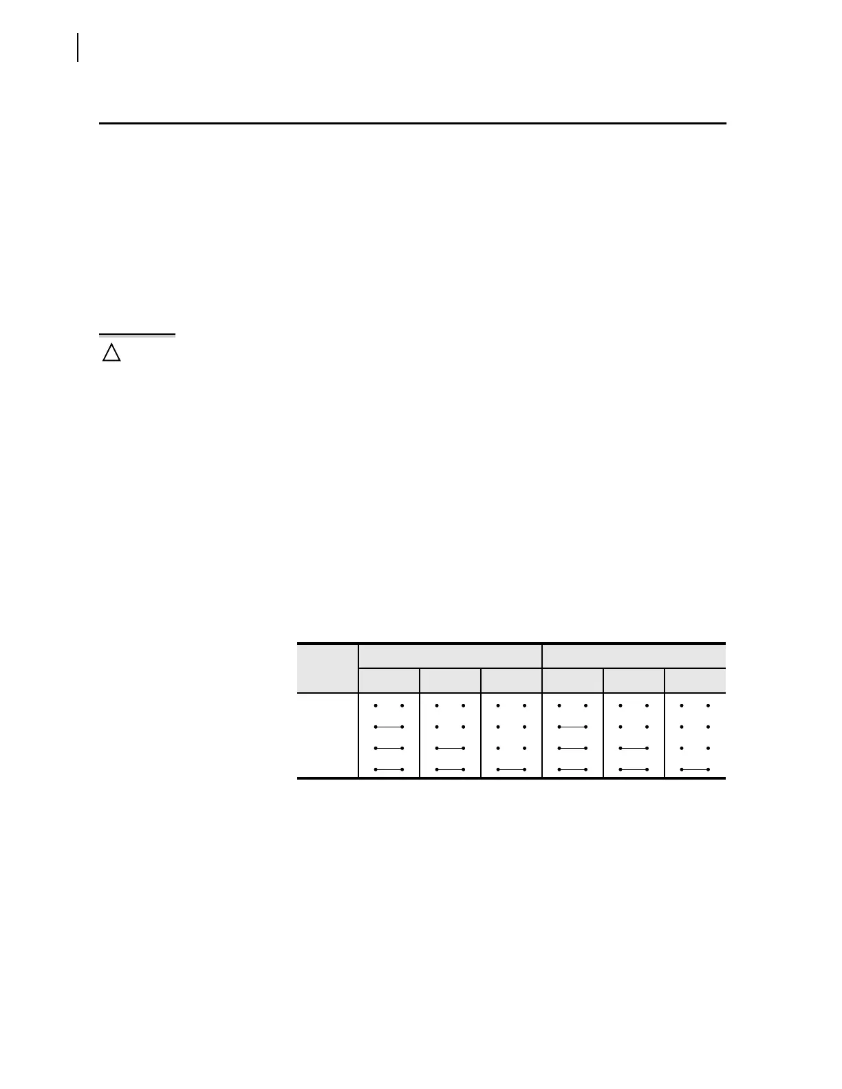
Step 6. Install or remove jumpers according to Table 2.1 to select the
desired control voltage level.
Step 7. Slide the draw-out assembly into the relay chassis.
Step 8. Reconnect the analog signal ribbon cable and the power supply
cable.
Step 9. Replace the relay front panel and reenergize the relay.
Output Contact
Jumpers
Jumpers JMP1 through JMP5 select the contact type for the output contacts.
Refer to Figure 2.6 on page 2.9. With a jumper in the A position, the
corresponding output contact is an “a” type output contact. An “a” type output
contact is open when the output contact coil is de-energized and closed when
the output contact coil is energized. With a jumper in the B position, the
corresponding output contact is a “b” type output contact. A “b” type output
contact is closed when the output contact coil is de-energized and open when
the output contact coil is energized. These jumpers are soldered in place.
In Figure 2.6 on page 2.9, note that the ALARM output contact is a “b”
contact and the other output contacts are all “a” contacts. This is how these
jumpers are configured in a standard relay shipment.
Table 2.1 Control Input Voltage Selection Jumper Positions
Control
Voltage
IN1 IN2
JMP6 JMP7 JMP8 JMP9 JMP10 JMP11
250 Vdc
125 Vdc
48 Vdc
24 Vdc