4.2
SEL-587Z Instruction Manual Date Code 20020903
Control Logic
Optoisolated Inputs
Optoisolated Inputs
Relay Word bits IN1 and IN2 follow debounced optoisolated inputs IN1 and
IN2, respectively,
IN1 is debounced input IN1
IN2 is debounced input IN2
EXAMPLE 4.1 Optoisolated Inputs
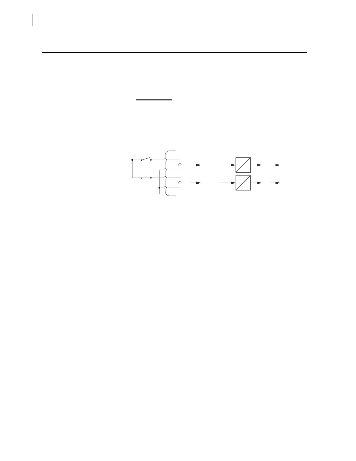
See Figure 4.1 for an example of an energized and de-energized
optoisolated input and corresponding Relay Word bit states. Note the
built-in pickup and dropout times of 0.25 cycle for energization or de-
energization debounce.
Figure 4.1 Example Operation of Optoisolated Inputs IN1 and IN2.
Configuration of the optoisolated inputs has the following format:
Relay variable (i.e., Relay Word bit, SEL
OGIC control equation) = IN1
You can initiate an event report in the SEL-587Z when any of the
feeders trip.
Step 1. After wiring the feeder initiating contacts in parallel, connect
the circuit to IN1.
Step 2. To start an event report, assert either Relay Word bit ER1 or
ER2.
The correct Input 1 assignment to assert ER1 is as follows:
ER1 = IN1 Event Report Trigger Condition 1
There are no optoisolated input settings such as IN1 = or IN2 =.
The relay polls the digital optoisolated inputs each processing
interval (1/8 of a power system cycle). A digital input change of state
occurs if the input remains in the changed state for two consecutive
processing intervals; otherwise, the software retains the previous
state.
The total time before the relay declares a change of optoisolated
input state is expressed as follows:
Equation 4.1
After 8.34 ms, the software updates the IN1 and IN2 Relay Word bits
to reflect the change of state.
0.25
0.25
0.25
0.25
ener
ize
de-ener
ize
lo
ical
lo
ical
-
+
o
e
l
Exam
le
wi
h
O
toisolator
In
ut
O
toisolator
In
ut State
Built in
Debounce
Timers
Rela
W
r
Bi
Rela
W
r
Bi
Time debounce time 2 processing intervals+=
1
0.25 60 Hz•
-------------------------------
èø
æö
22.083• ()+=
4.17 ms 4.17 ms+=
8.34 ms=